
User manual

Atmel-ICE [USER GUIDE]
42330A-MCU-07/2014
22
The aWire interface makes use the RESET wire of the AVR device to allow programming and debugging
functions. A special enable sequence is transmitted by the Atmel-ICE which disables the default RESET
functionality of the pin.
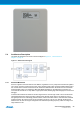
When designing an application PCB which includes an Atmel AVR with the aWire interface, it is recommended
to use the pinout as shown in Figure 4-5, “aWire Header Pinout” on page 22. The Atmel-ICE ships with both
100-mil and 50-mil adapters supporting this pinout.
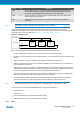
Figure 4-5. aWire Header Pinout
(RESET_N) DATA VCC
GND
1 2
aWire
(NC)
(NC)
(NC)
Tip
Since aWire is a half-duplex interface, a pull-up resistor on the RESET line in the order of 47k is
recommended to avoid false start-bit detection when changing direction.
The aWire interface can be used as both a programming and debugging interface, all features of the OCD
system available through the 10-pin JTAG interface can also be accessed using aWire.
4.2.3 PDI Physical
The Program and Debug Interface (PDI) is an Atmel proprietary interface for external programming and on-
chip debugging of a device. PDI Physical is a 2-pin interface providing a bi-directional half-duplex synchronous
communication with the target device.
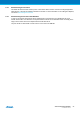
When designing an application PCB which includes an Atmel AVR with the PDI interface, the pinout shown in
Figure 4-6, “PDI Header Pinout” on page 22 should be used. One of the 6-pin adapters provided with the
Atmel-ICE kit can then be used to connect the Atmel-ICE probe to the application PCB.
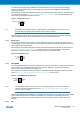
Figure 4-6. PDI Header Pinout
PDI_DATA
PDI_CLK
VCC
GND
1 2
PDI
(NC)
(NC)
4.2.4 debugWIRE
The debugWIRE interface was developed by Atmel for use on low pin-count devices. Unlike the JTAG interface
which uses four pins, debugWIRE makes use of just a single pin (RESET) for bi-directional half-duplex
asynchronous communication with the debugger tool.
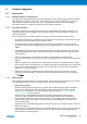
When designing an application PCB which includes an Atmel AVR with the debugWIRE interface, the pinout
shown in Figure 4-7, “debugWIRE (SPI) Header Pinout” on page 22 should be used.
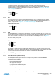
Figure 4-7. debugWIRE (SPI) Header Pinout
PDO/MISO
SCK
/RESET
VCC
PDI/MOSI
GND
1 2
SPI
Note
The debugWIRE interface can not be used as a programming interface. This means that the SPI
interface must also be available (as shown in Figure 4-8, “SPI Header Pinout” on page 23) in
order to program the target.
When the debugWIRE enable (DWEN) fuse is programmed and lock-bits are un-programmed, the debugWIRE
system within the target device is activated. The RESET pin is configured as a wire-AND (open-drain)
bi-directional I/O pin with pull-up enabled and becomes the communication gateway between target and
debugger.
4.2.5 SPI