
User manual


Atmel-ICE [USER GUIDE]
42330A-MCU-07/2014
21
Name Pin Description
VTG 1 Target voltage reference. The Atmel-ICE samples the target voltage on this pin in
order to power the level converters correctly. The Atmel-ICE draws less than 3mA
from this pin in debugWIRE mode and less than 1mA in other modes.
GND 3, 5, 9 Ground. All must be connected to ensure that the Atmel-ICE and the target device
share the same ground reference.
KEY 7 Connected internally to TRST pin on the AVR connector. Recommended as not
connected.
Tip
Remember to include a decoupling capacitor between pin 4 and GND.
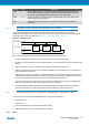
The JTAG interface allows for several devices to be connected to a single interface in a daisy-chain
configuration. The target devices must all be powered by the same supply voltage, share a common ground
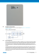
node, and must be connected as shown in Figure 4-4, “JTAG Daisy-Chain” on page 21.
Figure 4-4. JTAG Daisy-Chain
target
device
1
Atmel-ICE
TMS
TDI
TDO
TCK
target
device
2
target
device
3
When connecting devices in a daisy-chain, the following points must be considered:
● All devices must share a common ground, connected to GND on the Atmel-ICE probe
● All devices must be operating on the same target voltage. VTG on the Atmel-ICE must be connected to this
voltage
● TMS and TCK are connected in parallel; TDI and TDO are connected in a serial chain
● nSRST on the Atmel-ICE probe must be connected to RESET on the devices if any one of the devices in
the chain disables its JTAG port
● "Devices before" refers to the number of JTAG devices that the TDI signal has to pass through in the daisy
chain before reaching the target device. Similarly "devices after" is the number of devices that the signal
has to pass through after the target device before reaching the Atmel-ICE TDO pin
● "Instruction bits before" and "after" refers to the sum total of all JTAG devices' instruction register lengths
which are connected before and after the target device in the daisy chain
● The total IR length (instruction bits before + Atmel AVR IR length + instruction bits after) is limited to a
maximum of 256 bits. The number of devices in the chain is limited to 15 before and 15 after
Tip
Daisy chaining example: TDI → ATmega1280 → ATxmega128A1 → ATUC3A0512 → TDO
In order to connect to the Atmel AVR XMEGA device, the daisy chain settings are:
● Devices before: 1
● Devices after: 1
● Instruction bits before: 4 (8-bit AVR devices have 4 IR bits)
● Instruction bits after: 5 (32-bit AVR devices have 5 IR bits)
4.2.2 aWire