
User manual

Atmel-ICE [USER GUIDE]
42330A-MCU-07/2014
16
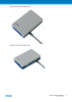
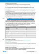
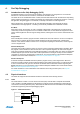
Connection to a 6-pin 50-mil SPI header
Use the adapter board (included in some kits) to connect to a standard 50-mil SPI header.
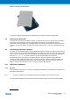
Connection to a custom 100-mil header
The 10-pin mini-squid cable should be used to connect between the Atmel-ICE AVR connector port and
the target board. Three connections are required, as described in Table 3-4, “Atmel-ICE debugWIRE Pin
Mapping” on page 16.
Although the debugWIRE interface only requires one signal line (RESET), Vcc and GND to operate correctly,
it is advised to have access to the full SPI connector so that the debugWIRE interface can be enabled and
disabled using SPI programming.
When the DWEN fuse is enabled the SPI interface is overridden internally in order for the OCD module to have
control over the RESET pin. The debugWIRE OCD is capable of disabling itself temporarily (using the button
on the debugging tab in the properties dialog in Atmel Studio), thus releasing control of the RESET line. The
SPI interface is then available again (only if the SPIEN fuse is programmed), allowing the DWEN fuse to be
un-programmed using the SPI interface. If power is toggled before the DWEN fuse is un-programmed, the
debugWIRE module will again take control of the RESET pin.
Note
It is highly advised to simply let Atmel Studio handle setting and clearing of the DWEN fuse.
It is not possible to use the debugWIRE interface if the lockbits on the target AVR device are programmed.
Always be sure that the lockbits are cleared before programming the DWEN fuse and never set the lockbits
while the DWEN fuse is programmed. If both the debugWIRE enable fuse (DWEN) and lockbits are set,
one can use High Voltage Programming to do a chip erase, and thus clear the lockbits. When the lockbits
are cleared the debugWIRE interface will be re-enabled. The SPI Interface is only capable of reading fuses,
reading signature and performing a chip erase when the DWEN fuse is un-programmed.
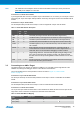
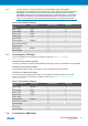
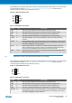
Table 3-4. Atmel-ICE debugWIRE Pin Mapping
Atmel-ICE AVR port pin Target pins Mini-squid pin
Pin 1 (TCK) 1
Pin 2 (GND) GND 2
Pin 3 (TDO) 3
Pin 4 (VTG) VTG 4
Pin 5 (TMS) 5
Pin 6 (nSRST) RESET 6
Pin 7 (Not connected) 7
Pin 8 (nTRST) 8
Pin 9 (TDI) 9
Pin 10 (GND) 0
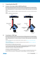
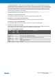
3.6 Connecting to a SPI Target
The recommended pinout for the 6-pin SPI connector is shown in Figure 4-8, “SPI Header
Pinout” on page 23.
Connection to a 6-pin 100-mil SPI header
Use the 6-pin 100-mil tap on the flat cable (included in some kits) to connect to a standard 100-mil SPI header.
Connection to a 6-pin 50-mil SPI header
Use the adapter board (included in some kits) to connect to a standard 50-mil SPI header.
Connection to a custom 100-mil header
The 10-pin mini-squid cable should be used to connect between the Atmel-ICE AVR connector port and the
target board. Six connections are required, as described in the table below.