
User manual

Atmel-ICE [USER GUIDE]
42330A-MCU-07/2014
15
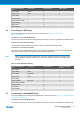
Atmel-ICE AVR port
pins
Target pins Mini-squid pin aWire pinout
Pin 3 (TDO) DATA 3 1
Pin 4 (VTG) VTG 4 2
Pin 5 (TMS) 5
Pin 6 (nSRST) 6
Pin 7 (Not connected) 7
Pin 8 (nTRST) 8
Pin 9 (TDI) 9
Pin 10 (GND) 0
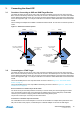
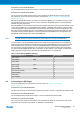
3.4 Connecting to a PDI Target
The recommended pinout for the 6-pin PDI connector is shown in Figure 4-6, “PDI Header
Pinout” on page 22.
Connection to a 6-pin 100-mil PDI header
Use the 6-pin 100-mil tap on the flat cable (included in some kits) to connect to a standard 100-mil PDI header.
Connection to a 6-pin 50-mil PDI header
Use the adapter board (included in some kits) to connect to a standard 50-mil PDI header.
Connection to a custom 100-mil header
The 10-pin mini-squid cable should be used to connect between the Atmel-ICE AVR connector port and the
target board. Four connections are required, as described in the table below.
Note
There is a difference from the JTAGICE mkII JTAG probe, where PDI_DATA is connected to pin 9.
The Atmel-ICE is compatible with the pinout used by the JTAGICE3, AVR ONE! and AVR Dragon
products.
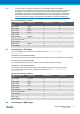
Table 3-3. Atmel-ICE PDI Pin Mapping
Atmel-ICE AVR port
pin
Target pins Mini-squid pin Atmel STK600 PDI
pinout
Pin 1 (TCK) 1
Pin 2 (GND) GND 2 6
Pin 3 (TDO) PDI_DATA 3 1
Pin 4 (VTG) VTG 4 2
Pin 5 (TMS) 5
Pin 6 (nSRST) PDI_CLK 6 5
Pin 7 (Not connected) 7
Pin 8 (nTRST) 8
Pin 9 (TDI) 9
Pin 10 (GND) 0
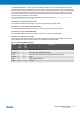
3.5 Connecting to a debugWIRE Target
The recommended pinout for the 6-pin debugWIRE (SPI) connector is shown in Figure 4-7, “debugWIRE (SPI)
Header Pinout” on page 22.
Connection to a 6-pin 100-mil SPI header
Use the 6-pin 100-mil tap on the flat cable (included in some kits) to connect to a standard 100-mil SPI header.