
Datasheet


978
SAM9X35 [DATASHEET]
11055E–ATARM–10-Mar-2014
44.5 Pin Name List
44.6 Product Dependencies
44.6.1 I/O Lines
The pins used for interfacing the compliant external devices may be multiplexed with PIO lines.
Before using the SSC receiver, the PIO controller must be configured to dedicate the SSC receiver I/O lines to the SSC
peripheral mode.
Before using the SSC transmitter, the PIO controller must be configured to dedicate the SSC transmitter I/O lines to the
SSC peripheral mode.
44.6.2 Power Management
The SSC is not continuously clocked. The SSC interface may be clocked through the Power Management Controller
(PMC), therefore the programmer must first configure the PMC to enable the SSC clock.
44.6.3 Interrupt
The SSC interface has an interrupt line connected to the interrupt controller. Handling interrupts requires programming
the interrupt controller before configuring the SSC.
All SSC interrupts can be enabled/disabled configuring the SSC Interrupt mask register. Each pending and unmasked
SSC interrupt will assert the SSC interrupt line. The SSC interrupt service routine can get the interrupt origin by reading
the SSC interrupt status register.
Table 44-1. I/O Lines Description
Pin Name Pin Description Type
RF Receiver Frame Synchro Input/Output
RK Receiver Clock Input/Output
RD Receiver Data Input
TF Transmitter Frame Synchro Input/Output
TK Transmitter Clock Input/Output
TD Transmitter Data Output
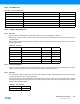
Table 44-2. I/O Lines
Instance Signal I/O Line Peripheral
SSC RD PA27 B
SSC RF PA29 B
SSC RK PA28 B
SSC TD PA26 B
SSC TF PA25 B
SSC TK PA24 B
Table 44-3. Peripheral IDs
Instance ID
SSC 28