
User manual

SAM9N12/CN11-EK User Guide 4-23
11186A–ATARM–29-Nov-12
4.4 Connectors
4.4.1 Power Supply
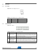
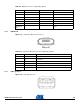
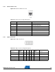
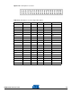
Figure 4-28. Power Supply Connector J1
4.4.2 JTAG/ICE Connector
Fi
gu
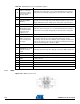
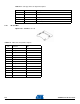
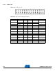
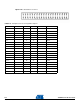
re 4-29. JTAG J4
Table 4-7. Power Supply Connector J1 Signal Descriptions
Pin Mnemonic Signal description
1 Center +5V
2Floating
3GND
Table 4-8. JTAG/ICE Connector J4 Signal Descriptions
Pin Mnemonic Signal Description
1 VTref. 3.3V power
This is the target reference voltage. It is used to check if the target has power,
to create the logic-level reference for the input comparators, and to control the
output logic levels to the target. It is normally fed from VDD on the target board
and must not have a series resistor.
2 Vsupply. 3.3V power
This pin is not connected in SAM-ICE. It is reserved for compatibility with other
equipment. Connect to VDD or leave open in target system.
3
nTRST TARGET
RESET - Active-low
output signal that
resets the target
JTAG Reset. Output from SAM-ICE to the reset signal on the target JTAG port.
Typically connected to nTRST on the target CPU. This pin is normally pulled
HIGH on the target to avoid unintentional resets when there is no connection.
4 GND Common ground.