
User manual


SAM9N12/CN11-EK User Guide 4-7
11186A–ATARM–29-Nov-12
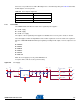
Connector J1 is provided for use with a DC adapter. It is a 2.5 mm male power jack. Table 4-2 below lists
the DC adapter connector pinouts.
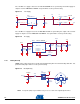
4.3.5 Power Rails
The SAM9N12/CN11-EK Board contains three regulated power supplies:
3.3V DC supply
1.8V DC supply
1.0V DC core supply
The outputs of these regulated power supplies are distributed as necessary to the circuits on boards.
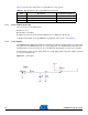
The USB supplies and the 5V input DC block are further regulated to 3.3V. The main 3.3V regulator is
b
a
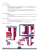
sed on a RICHTEK RT9018A low dropout regulator providing a fixed output of 3.3V. Its output is used
for:
VDDIOP0
VDDIOP1
VDDANA
VDDOSC
VDDUSB
VDDFUSE
When the 3.3V supply is present, power LED D10 is lit.
Test points TP2 to TP5 are used to perform testing.
Figure 4-6. 3.
3V Su
pply
Table 4-2. Power Input Configuration
PIN INPUT
1 (Center) Positive
2 No connection
3 (Outside) Ground
R1
100K
C5
1uF
C3
100nF
TP3
TP4
L2
220ohm at 100MHz
1 2
L3
220ohm at 100MHz
1 2
VDDIOP1
TP5
PWR_EN
R2
47K
TP1
R3
15K
+
C1
10uF
C2
1uF
MN1
R T9018A
PGOOD
1
EN
2
VIN
3
VDD
4
NC
5
VOUT
6
ADJ
7
GND
8
GND
9
+3V3 VDDIOP0
VDDANA
TP2
+
C4
10uF
L1
220ohm at 100MHz
1 2
+5V