
User manual

Bus Interface Unit
6-8 Copyright © 2001-2003 ARM Limited. All rights reserved. ARM DDI0198D
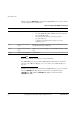
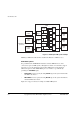
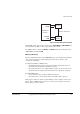
Figure 6-1 Multi-layer AHB system example
Multi-layer AHB is described in more detail in the Multi-layer AHB Overview.
Multi-AHB systems
It is possible that the ARM926EJ-S instruction and data AHB interfaces can be
connected to separate AHB systems, although there must be a mechanism to support
data side access to the instruction memory. Each AHB system can be running at
different frequencies. The ARM926EJ-S processor is able to cope with this by
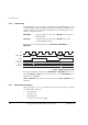
providing two HCLKEN inputs:
• DHCLKEN is used to specify the rising HCLK edge for the system in which the
data BIU is the master
• IHCLKEN is used to specify the rising HCLK edge for the system in which the
instruction BIU is the master.
Figure 6-2 on page 6-9 shows an example of a Multi-AHB system.
DMA
master
I-side
master
D-side
master
Interconnect
matrix
Input
stage
Decode
Mux
Mux
Mux
Mux
Input
stage
Input
stage
Decode
Decode
Slave
#1
Slave
#2
Slave
#3
Slave
#4
ARM926EJ-S
processor