
Datasheet


5
SAM9M10 [SUMMARY]
6355ES–ATARM–12-Mar-13
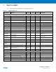
Shutdown, Wakeup Logic
SHDN Shut-Down Control Output VDDBU
Driven at 0V only.
0: The device is in backup
mode
1: The device is running (not in
backup mode).
WKUP Wake-Up Input Input VDDBU
Accept between 0V and
VDDBU.
ICE and JTAG
TCK Test Clock Input VDDIOP0
No pull-up resistor, Schmitt
trigger
TDI Test Data In Input VDDIOP0
No pull-up resistor, Schmitt
trigger
TDO Test Data Out Output VDDIOP0
TMS Test Mode Select Input VDDIOP0
No pull-up resistor, Schmitt
trigger
JTAGSEL JTAG Selection Input VDDBU Pull-down resistor (15 k
Ω).
RTCK Return Test Clock Output VDDIOP0
Reset/Test
NRST Microcontroller Reset
(2)
I/O Low VDDIOP0
Open drain output
Pull-Up resistor (100 kΩ),
Schmitt trigger
TST Test Mode Select Input VDDBU
Pull-down resistor (15 k
Ω),
Schmitt trigger
NTRST Test Reset Signal Input VDDIOP0
Pull-Up resistor (100 k
Ω),
Schmitt trigger
BMS Boot Mode Select Input VDDIOP0
must be connected to GND or
VDDIOP0.
Debug Unit - DBGU
DRXD Debug Receive Data Input
(1)
DTXD Debug Transmit Data Output
(1)
Advanced Interrupt Controller - AIC
IRQ External Interrupt Input Input
(1)
FIQ Fast Interrupt Input Input
(1)
PIO Controller - PIOA- PIOB - PIOC - PIOD - PIOE
PA0 - PA31 Parallel IO Controller A I/O
(1)
Pulled-up input at reset
(100k
Ω)
(3)
, Schmitt trigger
PB0 - PB31 Parallel IO Controller B I/O
(1)
Pulled-up input at reset
(100k
Ω)
(3)
, Schmitt trigger
PC0 - PC31 Parallel IO Controller C I/O
(1)
Pulled-up input at reset
(100k
Ω)
(3)
, Schmitt trigger
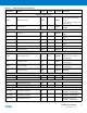
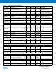
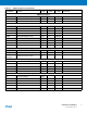
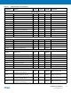
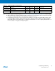
Table 3-1. Signal Description List (Continued)
Signal Name Function Type
Active
Level
Reference
Voltage Comments