
Datasheet


33
SAM9M10 [SUMMARY]
6355ES–ATARM–12-Mar-13
z Wait internal RC Startup Time for clock stabilization (software loop).
z Switch from 32768 Hz oscillator to internal RC oscillator by setting the bit OSCSEL to 0.
z Wait 5 slow clock cycles for internal resynchronization.
z Disable the 32768Hz oscillator by setting the bit OSC32EN to 0.
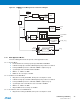
8.7 Power Management Controller
The Power Management Controller provides all the clock signals to the system.
PMC input clocks:
z UPLLCK: From UTMI PLL
z PLLACK From PLLA
z SLCK: slow clock from OSC32K or internal RC OSC
z MAINCK: from 12 MHz external oscillator
PMC output clocks
z Processor Clock PCK
z Master Clock MCK, in particular to the Matrix and the memory interfaces. The divider can be 1,2,3 or 4
z DDR system clock equal to 2xMCK
Note: DDR system clock is not available when Master Clock (MCK) equals Processor Clock (PCK).
z USB Host EHCI High speed clock (UPLLCK)
z USB OHCI clocks (UHP48M and UHP12M)
z Independent peripheral clocks, typically at the frequency of MCK
z Two programmable clock outputs: PCK0 and PCK1
This allows the software control of five flexible operating modes:
z Normal Mode, processor and peripherals running at a programmable frequency
z Idle Mode, processor stopped waiting for an interrupt
z Slow Clock Mode, processor and peripherals running at low frequency
z Standby Mode, mix of Idle and Backup Mode, peripheral running at low frequency, processor stopped waiting for
an interrupt
z Backup Mode, Main Power Supplies off, VDDBU powered by a battery