
Datasheet


22
SAM9M10 [SUMMARY]
6355ES–ATARM–12-Mar-13
z memory to memory transfer
z Peripheral to memory
z Memory to peripheral
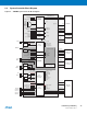
The DMA controller can handle the transfer between peripherals and memory and so receives the triggers from the
peripherals below. The hardware interface numbers are also given below in Table
6.6 Debug and Test Features
z ARM926 Real-time In-circuit Emulator
z Two real-time Watchpoint Units
z Two Independent Registers: Debug Control Register and Debug Status Register
z Test Access Port Accessible through JTAG Protocol
z Debug Communications Channel
z Debug Unit
z Two-pin UART
z Debug Communication Channel Interrupt Handling
z Chip ID Register
z IEEE1149.1 JTAG Boundary-scan on All Digital Pins.
Table 6-7. DMA Channel Definition
Instance Name T/R
DMA Channel HW
interface Number
MCI0 TX/RX 0
SPI0 TX 1
SPI0 RX 2
SPI1 TX 3
SPI1 RX 4
SSC0 TX 5
SSC0 RX 6
SSC1 TX 7
SSC1 RX 8
AC97C TX 9
AC97C RX 10
MCI1 TX/RX 13