
Datasheet


10
SAM9M10 [SUMMARY]
6355ES–ATARM–12-Mar-13
Notes: 1. Refer to peripheral multiplexing tables in Section 9.4 “Peripheral Signals Multiplexing on I/O Lines” for these signals.
2. When configured as an input, the NRST pin enables asynchronous reset of the device when asserted low. This allows
connection of a simple push button on the NRST pin as a system-user reset.
3. Programming of this pull-up resistor is performed independently for each I/O line through the PIO Controllers. After
reset, all the I/O lines default as inputs with pull-up resistors enabled, except those which are multiplexed with the
External Bus Interface signals that require to be enabled as Peripheral at reset. This is explicitly indicated in the col-
umn “Reset State” of the peripheral multiplexing tables.
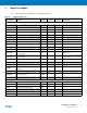
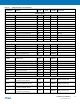
GPAD4-GPAD7 Analog Inputs Analog VDDANA
TSADTRG ADC Trigger Input VDDANA
TSADVREF ADC Reference Analog VDDANA
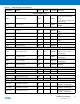
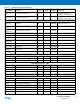
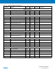
Table 3-1. Signal Description List (Continued)
Signal Name Function Type
Active
Level
Reference
Voltage Comments