
User manual


Connectors
6-12 AT91SAM9M10-G45-EK User Guide
6495B–ATARM–21-Apr-10
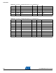
31 PE6 LCDDEN 32 PE2 LCDCC
33 PE0 DISPON 34 PE1 LCDMOD
35 PD14 GPIO1 36 PD15 GPIO2
37 GND (0V) 38 GND (0V)
39 VCC +3V3 power source 40 NC
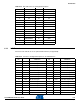
Table 6-16. Connector J18 Signal Description for an LCD Extension
Pin Mnemonic Pin Mnemonic
1 XM AD1XM 2 XP AD0XP
3 YM AD3YM 4 YP AD2YP
5 GND (0V) 6 GND (0V)
7 PD25 PD25 8 PD24 PD24
9 PD27 PD27 10 PD26 PD26
11 PD19 PD19 12 PD18 PD18
13 GND (0V) 14 GND (0V)
15 GND (0V) 16 +5V
17 GND (0V) 18 GND (0V)
19 VCC +3V3 power source 20 VCC +3V3 power source
Table 6-15. Connector J23 Signal Description for an LCD Extension
Pin Mnemonic Pin Mnemonic