
User manual

AT91SAM9M10-G45-EK User Guide 6-1
6495B–ATARM–21-Apr-10
Section 6
Connectors
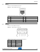
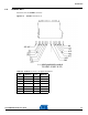
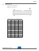
6.1 Power Supply
The SAM9M10-G45-EK evaluation board can be powered from a DC 5V power supply via the external
power supply jack (J2) shown in
Figure 6-1. The positive pole must be on J2 center pin.
Figure 6-1. Power Supply Connector J2
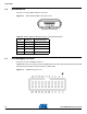
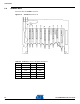
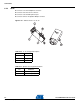
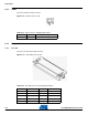
6.2 RS232 Connector with RTS/CTS Handshake Support
Connector J11 is the COM1 connector.
Figure 6-2. RS232 COM1 Connector J11
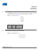
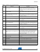
Table 6-1. Power Supply Connector J2 Signal Description
Pin Mnemonic Signal description
1 Center +5 VCC
2Gnd