
User manual


Configuration
AT91SAM9M10-G45-EK User Guide 5-3
6495B–ATARM–21-Apr-10
5.4 Miscellaneous Configuration Items
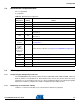
N.P = not populated
P = populated
5.5 PIO Configuration
5.5.1 Peripheral Signals Multiplexing on I/O Lines
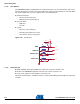
The AT91SAM9M10 product features 5 PIO controllers, PIOA, PIOB, PIOC, PIOD and PIOE, which mul-
tiplex the I/O lines of the peripheral set. Each PIO Controller controls up to 32 lines. Each line can be
assigned to one of two peripheral functions, A or B. The multiplexing tables in the following paragraphs
define how the I/O lines of peripherals A and B are multiplexed on the PIO Controllers.
5.5.2 Multiplexing on PIO Controller A (PIOA)
"R.Select" = connection selectable via an on-board resistor (default not populated)
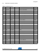
Table 5-3. Miscellaneous Configuration
Designation
Default
Setting Feature
R34 N.P JTAGSEL
R35 P Connect TSADVREF to VDDANA (may be used for specific filtering)
R36 P Connect GNDANA to GND (may be used for specific filtering)
R38 P Force TST pin to GND (chip is set in non-test mode = normal operation mode)
R63 N.P
Write protect NAND Flash (mount a 0-ohm resistor to write-protect the NAND
Flash device)
R68 N.P
Write protect serial DataFlash (mount a 0-ohm resistor to write-protect the serial
Flash device)
R75 N.P External clock Audio AC97 (mount a 0-ohm resistor to connect it)
R91,R92
R93,R94
ICE interface reset and clocking schemes (see
Section 5.1 ”JTAG/ICE
Configuration”
)
R100, R103
to R105,
R108 to
R110, R112,
R114, C174,
C175, Y5
Ethernet interface, MII mode (see
Section 5.2 ”ETHERNET Configuration” )
Y6, R184,
R186
N.P External 13 MHz oscillator (option) for the on-board video composite encoder
TP1 GND Test point
TP2 GND Test point
TP3 GND Test point
TP4 GND Test point