
User manual


Configuration
5-2 AT91SAM9M10-G45-EK User Guide
6495B–ATARM–21-Apr-10
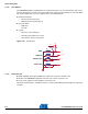
5.3 Jumpers Configuration
Two types of jumpers are used on the SAM9M10-G45-EK board:
2-pin jumpers with two possible settings:
– Fitted: the circuit is closed
– Not fitted: the circuit is open
3-pin jumpers with two possible positions, for which settings are presented in the following tables.
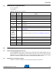
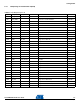
Table 5-2. Jumpers Configuration
Designation
Default
Setting Feature
J1
(combined
jumper array)
Closed J1-1 1-2 VDDUTMII 3V3
Closed J1-2 3-4 VDDUTIMC 1V
Closed J1-3 5-6 VDDCORE 1V
Closed J1-4 7-8 VDDPLLUTMI 1V
JP1 1-2 JP1
1-2 VDDIOP0 3V3
2-3 External power to VDDIOP0 3V3 nominal
JP2 1-2 JP2
1-2 VDDIOP1 3V3
2-3 External power to VDDIOP1 3V3 nominal
JP3 1-2 JP3
1-2 VDDIOP2 3V3
2-3 External power to VDDIOP2 3V3 nominal
JP4 Opened
Forces power on.
To use the software shutdown control, JP4 must be opened.
3V battery backup must be present and JP7 jumper set in position 1-2
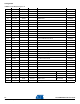
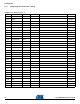
JP5 1-2 JP5
1-2 VDDIOM0 1V8
2-3 External power to VDDIOM0 1V8 nominal
JP6 1-2 JP6
1-2 VDDIOM1 1V8
2-3 External power to VDDIOM1 1V8 nominal
JP7 1-2 JP7
1-2 VDDBU Lithium 3V Battery
2-3 VDDBU 3.3V from regulator
JP8 Opened
BMS Enables Boot on the internal ROM; closed selects the boot from the external device connected
to NCS0
JP9 Closed Enables chip select access, Boot on the NCS0 (MN10 Flash)
JP10 Closed Enables chip select access, Boot on the NCS3 (MN11 NAND Flash)
JP11 Test point JP11.1: SO JP11.2: SI JP11.3: SCK
JP12 Closed Enables chip select access, Boot on the SPIO_NPCS0 (Serial DataFlash MN13)
JP13 Opened Set address A0 low (MN12 Serial EEPROM), enable Boot access.
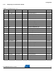
JP14 JP14.1 = Line_Out JP14.3 = AGND
JP15 Used to connect a Loudspeaker
JP16 Closed DISMDIX (MN18)
JP17-JP18 Test points Give access to the four GPIOs of WM9711L