
User manual


Board Description
4-18 AT91SAM9M10-G45-EK User Guide
6495B–ATARM–21-Apr-10
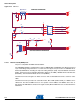
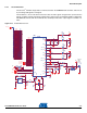
4.2.9 Software Controlled LEDs
Three users LED are provided for general use. The LEDs are connected to PIO port lines, allowing their
control through either GPIO or PWM control.
LEDs D1 to D3 are software controlled by PIO pins.
LEDs D4 to D6 indicate Ethernet traffic and link status. These are automatically managed by on-chip
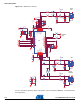
microcontroller hardware. See Section 7.1 ”Schematics” .
Figure 4-14. Software Controlled LEDs
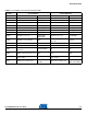
Table 4-3. Discrete LEDs
LED Description Comment
D1 Green LED User software controlled
D2 Green LED User software controlled
D3 Red LED User software controlled
D4 Yellow LED Indicates transmission or reception via Ethernet
D5 Green LED Indicates speed 100
D6 Green LED Is lit when a good link test has been detected
PB17
PB18
PB14
PB15
PB16
3V3
3V3
PD0
PD31
PD30
PB[14..18]
POWER LED
USER INTERFACE
UP
RIGHT
DOWN
PUSH
LEFT
C36
10n
C36
10n
D2
Green
D2
Green
1 2
C34
10n
C34
10n
R28
100R
R28
100R
R22 470RR22 470R
R25
470R
R25
470R
D1
Green
D1
Green
1
2
Q2
IRLML2402
Q2
IRLML2402
1
3
2
D3
Red
D3
Red
12
C33
10n
C33
10n
BP3BP3
JOYSTICK
1
2
3
4
5
6
C32
10n
C32
10n
C35
10n
C35
10n
R26
100k
R26
100k
R21 470RR21 470R