
User manual


Board Description
4-10 AT91SAM9M10-G45-EK User Guide
6495B–ATARM–21-Apr-10
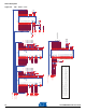
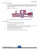
4.2.6 Debug Interface
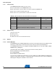
4.2.6.1 JTAG/ICE
Software debug is accessed by a standard 20-pin JTAG connection. This allows connection to a stan-
dard USB-to-JTAG in-circuit emulator.
Figure 4-7. JTAG Interface
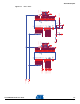
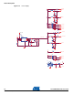
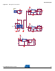
4.2.6.2 DBGU Com Port
This UART is connected to the DB-9 male socket through an RS-232 Transceiver (TXD and RXD only).
Figure 4-8. DBGU Com Port
TDI
RTCK
TDO
TMS
TCK
NTRST
NRST
3V3 3V3
3V3
NTRST
RTCK
TDI
TMS
TCK
TDO
NRST
ICE INTERFACE
R92 0RR92 0R
J13
HTST-110-01-SM-D
J13
HTST-110-01-SM-D
12
3
4
5
6
7
8
9
10
11
12
13
15
17
19
14
16
18
20
R94
0R
DNP
R94
0R
DNP
R93 0RR93 0R
R91 0R
DNP
R91 0R
DNP
RR43
100k
RR43
100k
1
2
3
4 5
6
7
8
3V3
3V3
PB13
PB12
SERIAL DEBUG PORT
C1+
V+
VCC
C1-
C2+
C2-V-
T
T
R
R
GND
MN15
ADM3202ARNZ
C1+
V+
VCC
C1-
C2+
C2-V-
GND
MN15
ADM3202ARNZ
1
16
3
4
5
15
11
10
12
98
13
7
14
2
6
R87
100k
R87
100k
C159
100n
C159
100n
R90 0RR90 0R
C163
100n
C163
100n
C157 100nC157 100n
R88
100k
R88
100k
C158 100nC158 100n
J10J10
5
4
3
2
1
9
8
7
6
10
11
C165 100nC165 100n