
Datasheet


949
SAM9M10 [DATASHEET]
6355F–ATARM–12-Mar-13
interrupts, or poll for the Channel Enable (DMAC_CHSR.ENABLE) bit until it is cleared by hardware, to
detect when the transfer is complete. If the DMAC is not in Row 1 as shown in Table 41-2 on page 938,
the following step is performed.
19. The DMAC fetches the next LLI from memory location pointed to by the current DMAC_DSCRx register,
and automatically reprograms the DMAC_DADDRx, DMAC_CTRLAx, DMAC_CTRLBx and
DMAC_DSCRx channel registers. Note that the DMAC_SADDRx is not re-programmed as the reloaded
value is used for the next DMAC buffer transfer. If the next buffer is the last buffer of the DMAC transfer
then the DMAC_CTRLBx and DMAC_DSCRx registers just fetched from the LLI should match Row 1 of
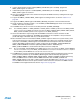
Table 41-2 on page 938. The DMAC transfer might look like that shown in Figure 41-11 on page 949.
Figure 41-11. Multi-buffer DMAC Transfer with Source Address Auto-reloaded and Linked List Destination Address
The DMAC Transfer flow is shown in Figure 41-12 on page 950.
Address of
Source Layer
Address of
Destination Layer
Source Buffers
Destination Buffers
SADDR
Buffer0
Buffer1
Buffer2
BufferN
DADDR(N)
DADDR(1)
DADDR(0)
DADDR(2)