
Datasheet


946
SAM9M10 [DATASHEET]
6355F–ATARM–12-Mar-13
in the DMAC transfer, then the buffer complete ISR (interrupt service routine) should clear the auto-
matic mode bit in the DMAC_CTRLBx.AUTO bit. This put the DMAC into Row 1 as shown in Table 41-
2 on page 938. If the next buffer is not the last buffer in the DMAC transfer, then the reload bits should
remain enabled to keep the DMAC in Row 4.
b. If the buffer complete interrupt is masked (DMAC_EBCIMR.BTC[x] = ‘1’, where x is the channel num-
ber), then hardware does not stall until it detects a write to the buffer complete interrupt enable
register DMAC_EBCIER register but starts the next buffer transfer immediately. In this case software
must clear the automatic mode bit in the DMAC_CTRLB to put the DMAC into ROW 1 of Table 41-2
on page 938 before the last buffer of the DMAC transfer has completed. The transfer is similar to that
shown in Figure 41-9 on page 946. The DMAC transfer flow is shown in Figure 41-10 on page 947.
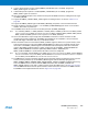
Figure 41-9. Multi-buffer DMAC Transfer with Source and Destination Address Auto-reloaded
Address of
Source Layer
Address of
Destination Layer
Source Buffers
Destination Buffers
BlockN
Block2
Block1
Block0
SADDR
DADDR