
Datasheet


902
SAM9M10 [DATASHEET]
6355F–ATARM–12-Mar-13
40.8 Conversion Results
When a conversion is completed, the resulting 8-bit or 10-bit digital value is right-aligned and stored in the
“TSADCC Channel Data Register x (x = 0..7)” of the current channel and in the “TSADCC Last Converted Data
Register”.
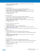
The channel EOC bit and the bit DRDY in the “TSADCC Status Register” are both set. If the PDC channel is
enabled, DRDY rising triggers a data transfer. In any case, either EOC and DRDY can trigger an interrupt.
Reading one of the “TSADCC Channel Data Register x (x = 0..7)” registers clears the corresponding EOC bit.
Reading “TSADCC Last Converted Data Register” clears the DRDY bit and the EOC bit corresponding to the last
converted channel.
Figure 40-5. EOCx and DRDY Flag Behavior
If the “TSADCC Channel Data Register x (x = 0..7)” is not read before further incoming data is converted, the cor-
responding Overrun Error (OVRE) flag is set in the “TSADCC Status Register”.
In the same way, new data converted when DRDY is high sets the bit GOVRE (General Overrun Error) in the
“TSADCC Status Register”.
The OVRE and GOVRE flags are automatically cleared when the “TSADCC Status Register”is read.
Conversion
Time
Read the ADC_CDRx
EOCx
DRDY
Read the ADC_LCDR
CHx
(ADC_CHSR)
(ADC_SR)
(ADC_SR)
Write the ADC_CR
with START = 1
Write the ADC_CR
with START = 1
SHTIM
Conversion
Time
SHTIM