
Datasheet


499
SAM9M10 [DATASHEET]
6355F–ATARM–12-Mar-13
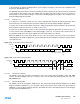
31.7.5.3 IrDA Demodulator
The demodulator is based on the IrDA Receive filter comprised of an 8-bit down counter which is loaded with the
value programmed in US_IF. When a falling edge is detected on the RXD pin, the Filter Counter starts counting
down at the Master Clock (MCK) speed. If a rising edge is detected on the RXD pin, the counter stops and is
reloaded with US_IF. If no rising edge is detected when the counter reaches 0, the input of the receiver is driven
low during one bit time.
Figure 31-35 illustrates the operations of the IrDA demodulator.
Figure 31-35. IrDA Demodulator Operations
As the IrDA mode uses the same logic as the ISO7816, note that the FI_DI_RATIO field in US_FIDI must be set to
a value higher than 0 in order to assure IrDA communications operate correctly.
3 686 400 57 600 4 0.00% 3.26
20 000 000 57 600 22 1.38% 3.26
32 768 000 57 600 36 1.25% 3.26
40 000 000 57 600 43 0.93% 3.26
3 686 400 38 400 6 0.00% 4.88
20 000 000 38 400 33 1.38% 4.88
32 768 000 38 400 53 0.63% 4.88
40 000 000 38 400 65 0.16% 4.88
3 686 400 19 200 12 0.00% 9.77
20 000 000 19 200 65 0.16% 9.77
32 768 000 19 200 107 0.31% 9.77
40 000 000 19 200 130 0.16% 9.77
3 686 400 9 600 24 0.00% 19.53
20 000 000 9 600 130 0.16% 19.53
32 768 000 9 600 213 0.16% 19.53
40 000 000 9 600 260 0.16% 19.53
3 686 400 2 400 96 0.00% 78.13
20 000 000 2 400 521 0.03% 78.13
32 768 000 2 400 853 0.04% 78.13
Table 31-13. IrDA Baud Rate Error (Continued)
Peripheral Clock Baud Rate CD Baud Rate Error Pulse Time
MCK
RXD
Receiver
Input
Pulse
Rejected
65432 6
1
65432 0
Pulse
Accepted
Counter
Value