
Datasheet


498
SAM9M10 [DATASHEET]
6355F–ATARM–12-Mar-13
The receiver and the transmitter must be enabled or disabled according to the direction of the transmission to be
managed.
To receive IrDA signals, the following needs to be done:
• Disable TX and Enable RX
• Configure the TXD pin as PIO and set it as an output at 0 (to avoid LED emission). Disable the internal pull-up
(better for power consumption).
• Receive data
31.7.5.1 IrDA Modulation
For baud rates up to and including 115.2 Kbits/sec, the RZI modulation scheme is used. “0” is represented by a
light pulse of 3/16th of a bit time. Some examples of signal pulse duration are shown in Table 31-12.
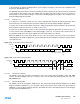
Figure 31-34 shows an example of character transmission.
Figure 31-34. IrDA Modulation
31.7.5.2 IrDA Baud Rate
Table 31-13 gives some examples of CD values, baud rate error and pulse duration. Note that the requirement on
the maximum acceptable error of ±1.87% must be met.
Table 31-12. IrDA Pulse Duration
Baud Rate Pulse Duration (3/16)
2.4 Kb/s 78.13 μs
9.6 Kb/s 19.53 μs
19.2 Kb/s 9.77 μs
38.4 Kb/s 4.88 μs
57.6 Kb/s 3.26 μs
115.2 Kb/s 1.63 μs
Bit Period
Bit Period
3
16
Start
Bit
Data Bits
Stop
Bit
0
0
0
0
0
1
11
1
1
Transmitter
Output
TXD
Table 31-13. IrDA Baud Rate Error
Peripheral Clock Baud Rate CD Baud Rate Error Pulse Time
3 686 400 115 200 2 0.00% 1.63
20 000 000 115 200 11 1.38% 1.63
32 768 000 115 200 18 1.25% 1.63
40 000 000 115 200 22 1.38% 1.63