
Datasheet


1309
SAM9M10 [DATASHEET]
6355F–ATARM–12-Mar-13
47.12 Core Power Supply POR Characteristics
47.12.1 Power Sequence Requirements
The SAM9M10 board design must comply with the power-up guidelines below to guarantee reliable operation of
the device. Any deviation from these sequences may prevent the device from booting.
47.12.2 Power-Up Sequence
Figure 47-2. VDDCORE and VDDIO Constraints at Startup
VDDCORE and VDDBU are controlled by internal POR (Power-On-Reset) to guarantee that these power sources
reach their target values prior to the release of POR.
• VDDIOP must be ≥ VIH (refer to DC characteristics, Table 47-2, for more details) within (Tres + T1) after
VDDCORE has reached V
th+
.
• VDDIOM must reach VOH (refer to DC characteristics, Table 47-2, for more details) within (Tres +T1 +T2) after
VDDCORE has reached V
th+
–T
RES
is a POR characteristic
– T1 = 3 x T
SLCK
– T2 = 16 x T
SLCK
The T
SLCK
min (22 μs) is obtained for the maximum frequency of the internal RC oscillator (44KHz).
–T
RES
= 30 μs
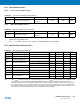
Table 47-25. Power-On-Reset Characteristics
Symbol Parameter Conditions Min Typ Max Units
V
th+
Threshold Voltage Rising Minimum Slope of +2.0V/30ms 0.5 0.7 0.89 V
V
th-
Threshold Voltage Falling 0.4 0.6 0.85 V
T
RES
Reset Time 30 70 130 μs
VDD (V)
Core Supply POR Output
VDDIOtyp
Vih
Vt h+
t
SLCK
<--- Tres --->
VDDIO > Vih
VDDCORE
VDDIO
< T1 >
VDDCOREtyp
Voh
VDDIO > Voh
<------------ T2----------->