
Datasheet


967
SAM9G15 [DATASHEET]
11052D–ATARM–31-Oct-12
44.6.2.4 DMA Dynamic Linking of a New Transfer Descriptor
1. Write the new descriptor structure in the system memory.
2. Write the address of the new structure in the CHXHEAD register.
3. Add the new structure to the queue of descriptors by writing one to the A2QEN field of the CHXCHER register.
4. The new descriptor will be added to the queue on the next frame.
5. An interrupt will be raised if unmasked, when the head descriptor structure has been loaded by the DMA channel.
44.6.2.5 DMA Interrupt Generation
The DMA controller operation sets the following interrupt flags in the interrupt status register CHXISR:
z DMA field indicates that the DMA transfer is completed.
z DSCR field indicates that the descriptor structure is loaded in the DMA controller.
z ADD field indicates that a descriptor has been added to the descriptor queue.
z DONE field indicates that the channel transfer has terminated and the channel is automatically disabled.
44.6.2.6 DMA Address Alignment Requirements
When programming the DSCR.CHXADDR field of the DSCR structure the following requirement must be met.
Table 44-5. DMA address alignment when CLUT Mode is selected
CLUT Mode DMA Address Alignment
1 bpp 8 bit
2 bpp 8 bit
4 bpp 8 bit
8 bpp 8 bit
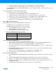
Table 44-6. DMA address alignment when RGB Mode is selected
RGB Mode DMA Address Alignment
12 bpp RGB 444 16 bit
16 bpp ARGB 4444 16 bit
16 bpp RGBA 4444 16 bit
16 bpp RGB 565 16 bit
16 bpp TRGB 1555 16 bit
18 bpp RGB 666 32 bit
18 bpp RGB 666 PACKED 8 bit
19 bpp TRGB 1666 32 bit
19 bpp TRGB 1666 8 bit
24 bpp RGB 888 32 bit
24 bpp RGB 888 PACKED 8 bit
25 bpp TRGB 1888 32 bit
32 bpp ARGB 8888 32 bit
32 bpp RGBA 8888 32 bit