
Datasheet


798
SAM9G15 [DATASHEET]
11052D–ATARM–31-Oct-12
LIN provides cost efficient bus communication where the bandwidth and versatility of CAN are not required.
The LIN Mode enables processing LIN frames with a minimum of action from the microprocessor.
39.7.8.1 Modes of Operation
The USART can act either as a LIN Master node or as a LIN Slave node.
The node configuration is chosen by setting the USART_MODE field in the USART Mode register (US_MR):
z LIN Master Node (USART_MODE=0xA)
z LIN Slave Node (USART_MODE=0xB)
In order to avoid unpredicted behavior, any change of the LIN node configuration must be followed by a software reset of
the transmitter and of the receiver (except the initial node configuration after a hardware reset). (See Section 39.7.8.3)
39.7.8.2 Baud Rate Configuration
See “Baud Rate in Asynchronous Mode” on page 771.
The baud rate is configured in the Baud Rate Generator register (US_BRGR).
39.7.8.3 Receiver and Transmitter Control
See “Receiver and Transmitter Control” on page 775.
39.7.8.4 Character Transmission
See “Transmitter Operations” on page 775.
39.7.8.5 Character Reception
See “Receiver Operations” on page 782.
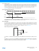
39.7.8.6 Header Transmission (Master Node Configuration)
All the LIN Frames start with a header which is sent by the master node and consists of a Synch Break Field, Synch Field
and Identifier Field.
So in Master node configuration, the frame handling starts with the sending of the header.
The header is transmitted as soon as the identifier is written in the LIN Identifier register (US_LINIR). At this moment the
flag TXRDY falls.
The Break Field, the Synch Field and the Identifier Field are sent automatically one after the other.
The Break Field consists of 13 dominant bits and 1 recessive bit, the Synch Field is the character 0x55 and the Identifier
corresponds to the character written in the LIN Identifier Register (US_LINIR). The Identifier parity bits can be
automatically computed and sent (see Section 39.7.8.9).
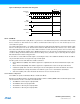
The flag TXRDY rises when the identifier character is transferred into the Shift Register of the transmitter.
As soon as the Synch Break Field is transmitted, the flag LINBK in the Channel Status register (US_CSR) is set to 1.
Likewise, as soon as the Identifier Field is sent, the flag LINID in the Channel Status register (US_CSR) is set to 1. These
flags are reset by writing the bit RSTSTA to 1 in the Control register (US_CR).