
Datasheet


676
SAM9G15 [DATASHEET]
11052D–ATARM–31-Oct-12
36.6.12 External Event/Trigger Conditions
An external event can be programmed to be detected on one of the clock sources (XC0, XC1, XC2) or TIOB. The
external event selected can then be used as a trigger.
The EEVT parameter in TC_CMR selects the external trigger. The EEVTEDG parameter defines the trigger edge for
each of the possible external triggers (rising, falling or both). If EEVTEDG is cleared (none), no external event is defined.
If TIOB is defined as an external event signal (EEVT = 0), TIOB is no longer used as an output and the compare register
B is not used to generate waveforms and subsequently no IRQs. In this case the TC channel can only generate a
waveform on TIOA.
When an external event is defined, it can be used as a trigger by setting bit ENETRG in TC_CMR.
As in Capture Mode, the SYNC signal and the software trigger are also available as triggers. RC Compare can also be
used as a trigger depending on the parameter WAVSEL.
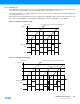
36.6.13 Output Controller
The output controller defines the output level changes on TIOA and TIOB following an event. TIOB control is used only if
TIOB is defined as output (not as an external event).
The following events control TIOA and TIOB: software trigger, external event and RC compare. RA compare controls
TIOA and RB compare controls TIOB. Each of these events can be programmed to set, clear or toggle the output as
defined in the corresponding parameter in TC_CMR.
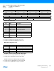
36.7 Timer Counter (TC) User Interface
Notes: 1. Channel index ranges from 0 to 2.
2. Read-only if WAVE = 0
Table 36-5. Register Mapping
Offset
(1)
Register Name Access Reset
0x00 + channel * 0x40 + 0x00 Channel Control Register TC_CCR Write-only –
0x00 + channel * 0x40 + 0x04 Channel Mode Register TC_CMR Read-write 0
0x00 + channel * 0x40 + 0x08 Reserved
0x00 + channel * 0x40 + 0x0C Reserved
0x00 + channel * 0x40 + 0x10 Counter Value TC_CV Read-only 0
0x00 + channel * 0x40 + 0x14 Register A TC_RA Read-write
(2)
0
0x00 + channel * 0x40 + 0x18 Register B TC_RB Read-write
(2)
0
0x00 + channel * 0x40 + 0x1C Register C TC_RC Read-write 0
0x00 + channel * 0x40 + 0x20 Status Register TC_SR Read-only 0
0x00 + channel * 0x40 + 0x24 Interrupt Enable Register TC_IER Write-only –
0x00 + channel * 0x40 + 0x28 Interrupt Disable Register TC_IDR Write-only –
0x00 + channel * 0x40 + 0x2C Interrupt Mask Register TC_IMR Read-only 0
0xC0 Block Control Register TC_BCR Write-only –
0xC4 Block Mode Register TC_BMR Read-write 0
0xC8 - 0xD4 Reserved
0xD8 Reserved
0xE4 Reserved
0xE8 - 0xFC Reserved – – –