
User manual

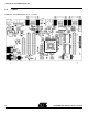
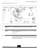
Table Of Contents

AT91SAM9260-EK Evaluation Board User Guide i
6234C–ATARM–22-Mar-07
Table of Contents
Section 1
Overview...............................................................................................1-1
1.1 Scope........................................................................................................1-1
1.2 Deliverables ..............................................................................................1-1
1.3 AT91SAM9260-EK Evaluation Board .......................................................1-1
Section 2
Setting Up the AT91SAM9260-EK Board .............................................2-1
2.1 Electrostatic Warning ................................................................................2-1
2.2 Requirements............................................................................................2-1
2.3 Layout .......................................................................................................2-2
2.4 Powering Up the Board.............................................................................2-3
2.5 Backup Power Supply...............................................................................2-3
2.6 Getting Started..........................................................................................2-3
2.7 AT91SAM9260-EK Block Diagram ...........................................................2-4
Section 3
Board Description .................................................................................3-1
3.1 AT91SAM9260 Microcontroller .................................................................3-1
3.2 AT91SAM9260 Block Diagram .................................................................3-4
3.3 Microcontroller...........................................................................................3-5
3.4 Memory .....................................................................................................3-5
3.5 Clock Circuitry...........................................................................................3-5
3.6 Reset Circuitry...........................................................................................3-5
3.7 Shutdown Controller..................................................................................3-5
3.8 Power Supply Circuitry..............................................................................3-5
3.9 Remote Communication............................................................................3-5
3.10 Audio Stereo Interface ..............................................................................3-6
3.11 User Interface ...........................................................................................3-6
3.12 Debug Interface ........................................................................................3-6
3.13 Expansion Slot ..........................................................................................3-6
3.14 PIO Usage ................................................................................................3-7
Section 4
Configuration ........................................................................................4-1
4.1 Jumpers ....................................................................................................4-1
4.2 JTAG/ICE..................................................................................................4-2
4.3 Microcontroller Clock.................................................................................4-2
4.4 Memory .....................................................................................................4-2
4.5 Ethernet ....................................................................................................4-3
4.6 Miscellaneous ...........................................................................................4-3