
Datasheet


226
SAM7X Series [DATASHEET]
6120K–ATARM–11-Feb-14
27.5 I/O Lines Programming Example
The programing example as shown in Table 27-1 below is used to define the following configuration.
4-bit output port on I/O lines 0 to 3, (should be written in a single write operation), open-drain, with pull-up resistor
Four output signals on I/O lines 4 to 7 (to drive LEDs for example), driven high and low, no pull-up resistor
Four input signals on I/O lines 8 to 11 (to read push-button states for example), with pull-up resistors, glitch filters
and input change interrupts
Four input signals on I/O line 12 to 15 to read an external device status (polled, thus no input change interrupt), no
pull-up resistor, no glitch filter
I/O lines 16 to 19 assigned to peripheral A functions with pull-up resistor
I/O lines 20 to 23 assigned to peripheral B functions, no pull-up resistor
I/O line 24 to 27 assigned to peripheral A with Input Change Interrupt and pull-up resistor
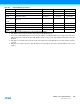
Table 27-1. Programming Example
Register Value to be Written
PIO_PER 0x0000 FFFF
PIO_PDR 0x0FFF 0000
PIO_OER 0x0000 00FF
PIO_ODR 0x0FFF FF00
PIO_IFER 0x0000 0F00
PIO_IFDR 0x0FFF F0FF
PIO_SODR 0x0000 0000
PIO_CODR 0x0FFF FFFF
PIO_IER 0x0F00 0F00
PIO_IDR 0x00FF F0FF
PIO_MDER 0x0000 000F
PIO_MDDR 0x0FFF FFF0
PIO_PUDR 0x00F0 00F0
PIO_PUER 0x0F0F FF0F
PIO_ASR 0x0F0F 0000
PIO_BSR 0x00F0 0000
PIO_OWER 0x0000 000F
PIO_OWDR 0x0FFF FFF0