
Datasheet


134
SAM7X Series [DATASHEET]
6120K–ATARM–11-Feb-14
22. Peripheral DMA Controller (PDC)
22.1 Overview
The Peripheral DMA Controller (PDC) transfers data between on-chip serial peripherals such as the UART, USART,
SSC, SPI, MCI and the on- and off-chip memories. Using the Peripheral DMA Controller avoids processor intervention
and removes the processor interrupt-handling overhead. This significantly reduces the number of clock cycles required
for a data transfer and, as a result, improves the performance of the microcontroller and makes it more power efficient.
The PDC channels are implemented in pairs, each pair being dedicated to a particular peripheral. One channel in the pair
is dedicated to the receiving channel and one to the transmitting channel of each UART, USART, SSC and SPI.
The user interface of a PDC channel is integrated in the memory space of each peripheral. It contains:
A 32-bit memory pointer register
A 16-bit transfer count register
A 32-bit register for next memory pointer
A 16-bit register for next transfer count
The peripheral triggers PDC transfers using transmit and receive signals. When the programmed data is transferred, an
end of transfer interrupt is generated by the corresponding peripheral.
22.2 Block Diagram
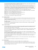
Figure 22-1. Block Diagram
22.3 Functional Description
22.3.1 Configuration
The PDC channels user interface enables the user to configure and control the data transfers for each channel. The user
interface of a PDC channel is integrated into the user interface of the peripheral (offset 0x100), which it is related to.
Per peripheral, it contains four 32-bit Pointer Registers (RPR, RNPR, TPR, and TNPR) and four 16-bit Counter Registers
(RCR, RNCR, TCR, and TNCR).
Control
PDC Channel 0
PDC Channel 1
THR
RHR
Control
Status & Control
Peripheral
Peripheral DMA Controller
Memory
Controller