
User manual


AT91SAM7X-EK Evaluation Board User Guide 4-1
6195E–ATARM–22-Mar-07
Section 4
Configuration Straps
4.1 Configuration
Straps
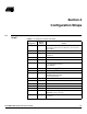
Table 4-1. Configuration Jumpers and Straps
Designation
Default
Setting Feature
J8 Opened Erases all internal Flash memory when the board is
powered. To do that, the user will have to close the J8 at
least 200 ms.
J9 Opened Do not use: Factory test mode. J9 is not populated
J10 Opened Selects ICE mode or JTAG mode (Closed). J10 is not
populated.
J11 Closed VDDIN Jumper
(1)
J12 Closed VDDFLASH Jumper
(1)
J13 1-2 ADVREF Jumper select
1-2: 3.00V Voltage reference
2-3: VDDANA
J14 Closed VDDCORE Jumper
(1)
J15 Closed VDDIO Jumper
(1)
J17 Opened External XIN clock input.
S4 and S5 must be open.
J17 is not populated.
J18 Closed VDDPLL Jumper
(1)
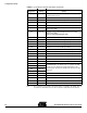
J19 Closed Enables the use of the NPCS00 (PA12).
J21 Closed Enables 120 ohms CAN bus resistance termination.
J28 Closed Enables Ethernet Auto MDIX control.
S1 Closed Enables permanent pull up on USB DP.
S2 Closed The System Reset signal (NRST) is connected to the
ICE/JTAG socket (J7, pin 15).
S3 Opened Disables 5V (VUSB) power supply on J16 extension
connector.