AT91SAM ARM-based Flash MCU SAM7S512 SAM7S256 SAM7S128 SAM7S64 SAM7S321 SAM7S32 SAM7S161 SAM7S16 Summary Features • Incorporates the ARM7TDMI® ARM® Thumb® Processor • • • • • • • This is a summary document. The complete document is available on the Atmel website at www.atmel.com.
• Debug Unit (DBGU) • • • • • • • • • • • • • • • • • – 2-wire UART and Support for Debug Communication Channel interrupt, Programmable ICE Access Prevention – Mode for General Purpose 2-wire UART Serial Communication Periodic Interval Timer (PIT) – 20-bit Programmable Counter plus 12-bit Interval Counter Windowed Watchdog (WDT) – 12-bit key-protected Programmable Counter – Provides Reset or Interrupt Signals to the System – Counter May Be Stopped While the Processor is in Debug State or in Idle M
• Fully Static Operation: Up to 55 MHz at 1.65V and 85⋅ C Worst Case Conditions • Available in 64-lead LQFP Green or 64-pad QFN Green Package (SAM7S512/256/128/64/321/161) and 48-lead LQFP Green or 48-pad QFN Green Package (SAM7S32/16) 1. Description Atmel’s SAM7S is a series of low pincount Flash microcontrollers based on the 32-bit ARM RISC processor. It features a high-speed Flash and an SRAM, a large set of peripherals, including a USB 2.
2. Block Diagram Figure 2-1. SAM7S512/256/128/64/321/161 Block Diagram TDI TDO TMS TCK ICE JTAG SCAN ARM7TDMI Processor JTAGSEL 1.
Figure 2-2. SAM7S32/16 Block Diagram TDI TDO TMS TCK ICE JTAG SCAN ARM7TDMI Processor JTAGSEL 1.
3. Signal Description Table 3-1. Signal Description List Signal Name Function Type Active Level Comments Power VDDIN Voltage and ADC Regulator Power Supply Input Power 3.0 to 3.6V VDDOUT Voltage Regulator Output Power 1.85V nominal VDDFLASH Flash Power Supply Power 3.0V to 3.6V VDDIO I/O Lines Power Supply Power 3.0V to 3.6V or 1.65V to 1.95V VDDCORE Core Power Supply Power 1.65V to 1.95V VDDPLL PLL Power 1.65V to 1.
Table 3-1.
Table 3-1.
4. Package and Pinout The SAM7S512/256/128/64/321 are available in a 64-lead LQFP or 64-pad QFN package. The SAM7S161 is available in a 64-Lead LQFP package. The SAM7S32/16 are available in a 48-lead LQFP or 48-pad QFN package. 4.1 64-lead LQFP and 64-pad QFN Package Outlines Figure 4-1 and Figure 4-2 show the orientation of the 64-lead LQFP and the 64-pad QFN package. A detailed mechanical description is given in the section Mechanical Characteristics of the full datasheet. Figure 4-1.
4.2 64-lead LQFP and 64-pad QFN Pinout Table 4-1.
4.3 48-lead LQFP and 48-pad QFN Package Outlines Figure 4-3 and Figure 4-4 show the orientation of the 48-lead LQFP and the 48-pad QFN package. A detailed mechanical description is given in the section Mechanical Characteristics of the full datasheet. Figure 4-3. 48-lead LQFP Package (Top View) 36 25 37 24 48 13 1 12 Figure 4-4. 48-pad QFN Package (Top View) 36 25 37 24 48 13 1 4.4 12 48-lead LQFP and 48-pad QFN Pinout Table 4-2.
5. Power Considerations 5.1 Power Supplies The SAM7S Series has six types of power supply pins and integrates a voltage regulator, allowing the device to be supplied with only one voltage. The six power supply pin types are: z VDDIN pin. It powers the voltage regulator and the ADC; voltage ranges from 3.0V to 3.6V, 3.3V nominal. z VDDOUT pin. It is the output of the 1.8V voltage regulator. z VDDIO pin. It powers the I/O lines and the USB transceivers; dual voltage range is supported. Ranges from 3.
Figure 5-1. 3.3V System Single Power Supply Schematic VDDFLASH Power Source ranges from 4.5V (USB) to 18V DC/DC Converter VDDIO VDDIN Voltage Regulator 3.
6. I/O Lines Considerations 6.1 JTAG Port Pins TMS, TDI and TCK are schmitt trigger inputs. TMS and TCK are 5-V tolerant, TDI is not. TMS, TDI and TCK do not integrate a pull-up resistor. TDO is an output, driven at up to VDDIO, and has no pull-up resistor. The JTAGSEL pin is used to select the JTAG boundary scan when asserted at a high level. The JTAGSEL pin integrates a permanent pull-down resistor of about 15 kΩ to GND, so that it can be left unconnected for normal operations. 6.
SAM7S Series [DATASHEET] 6175KS–ATARM–25-Oct-12 15
7. Processor and Architecture 7.1 ARM7TDMI Processor z RISC processor based on ARMv4T Von Neumann architecture z z z 7.2 Two instruction sets z ARM® high-performance 32-bit instruction set z Thumb® high code density 16-bit instruction set Three-stage pipeline architecture z Instruction Fetch (F) z Instruction Decode (D) z Execute (E) Debug and Test Features z z z 7.3 Runs at up to 55 MHz, providing 0.
7.
8. Memories 8.
z z Fast access time, 30 MHz single-cycle access in Worst Case conditions z Page programming time: 6 ms, including page auto-erase z Page programming without auto-erase: 3 ms z Full chip erase time: 15 ms z 10,000 write cycles, 10-year data retention capability z 16 lock bits, protecting 16 sectors of 32 pages z Protection Mode to secure contents of the Flash 16 Kbytes of Fast SRAM z 8.
Figure 8-1. SAM SAM7S512/256/128/64/321/32/161/16 Memory Mapping Internal Memory Mapping Note: (1) Can be Flash or SRAM depending on REMAP.
8.7 Memory Mapping 8.7.1 Internal SRAM z The SAM7S512 embeds a high-speed 64-Kbyte SRAM bank. z The SAM7S256 embeds a high-speed 64-Kbyte SRAM bank. z The SAM7S128 embeds a high-speed 32-Kbyte SRAM bank. z The SAM7S64 embeds a high-speed 16-Kbyte SRAM bank. z The SAM7S321 embeds a high-speed 8-Kbyte SRAM bank. z The SAM7S32 embeds a high-speed 8-Kbyte SRAM bank. z The SAM7S161 embeds a high-speed 4-Kbyte SRAM bank.
8.8 Embedded Flash 8.8.1 Flash Overview z The Flash of the SAM7S512 is organized in two banks (dual plane) of 1024 pages of 256 bytes. The 524,288 bytes are organized in 32-bit words. z The Flash of the SAM7S256 is organized in 1024 pages (single plane) of 256 bytes. The 262,144 bytes are organized in 32-bit words. z The Flash of the SAM7S128 is organized in 512 pages (single plane) of 256 bytes. The 131,072 bytes are organized in 32-bit words.
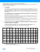
8.8.3 Lock Regions 8.8.3.1 SAM7S512 Two Embedded Flash Controllers each manage 16 lock bits to protect 16 regions of the flash against inadvertent flash erasing or programming commands. The SAM7S512 contains 32 lock regions and each lock region contains 64 pages of 256 bytes. Each lock region has a size of 16 Kbytes.
The 8 NVM bits are software programmable through the EFC User Interface. The command “Set Lock Bit” enables the protection. The command “Clear Lock Bit” unlocks the lock region. Asserting the ERASE pin clears the lock bits, thus unlocking the entire Flash. 8.8.3.6 SAM7S161/16 The Embedded Flash Controller manages 8 lock bits to protect 8 regions of the flash against inadvertent flash erasing or programming commands. The SAM7S161/16 contains 8 lock regions and each lock region contains 32 pages of 64 bytes.
8.8.6 Calibration Bits Eight NVM bits are used to calibrate the brownout detector and the voltage regulator. These bits are factory configured and cannot be changed by the user. The ERASE pin has no effect on the calibration bits. 8.9 Fast Flash Programming Interface The Fast Flash Programming Interface allows programming the device through either a serial JTAG interface or through a multiplexed fully-handshaked parallel port. It allows gang-programming with market-standard industrial programmers.
Figure 9-1.
Figure 9-2. System Controller Block Diagram (SAM7S32/16) Interrupt Controller periph_irq[2..14] proc_nreset ARM7TDM PCK int debug pit_irq rtt_irq wdt_irq dbgu_irq pmc_irq rstc_irq power_on_reset force_ntrst dbgu_irq MCK periph_nreset Debug Unit force_ntrst dbgu_txd dbgu_rxd security_bit MCK debug periph_nreset SLCK periph_nreset Periodic Interval Timer pit_irq Real-Time Timer rtt_irq Watchdog Timer wdt_irq flash_poe flash_wrdis cal SLCK debug idle proc_nreset cal gpnvm[0] gpnvm[0..
9.1 Reset Controller The Reset Controller is based on a power-on reset cell and one brownout detector. It gives the status of the last reset, indicating whether it is a power-up reset, a software reset, a user reset, a watchdog reset or a brownout reset. In addition, it controls the internal resets and the NRST pin open-drain output. It allows to shape a signal on the NRST line, guaranteeing that the length of the pulse meets any requirement.
9.2 Clock Generator The Clock Generator embeds one low-power RC Oscillator, one Main Oscillator and one PLL with the following characteristics: z RC Oscillator ranges between 22 kHz and 42 kHz z Main Oscillator frequency ranges between 3 and 20 MHz z Main Oscillator can be bypassed z PLL output ranges between 80 and 220 MHz It provides SLCK, MAINCK and PLLCK. Figure 9-3.
Figure 9-4. Power Management Controller Block Diagram Processor Clock Controller Master Clock Controller SLCK MAINCK PLLCK PCK int Idle Mode Prescaler /1,/2,/4,...,/64 MCK Peripherals Clock Controller periph_clk[2..14] ON/OFF Programmable Clock Controller SLCK MAINCK PLLCK Prescaler /1,/2,/4,...,/64 USB Clock Controller ON/OFF PLLCK 9.
z z z One set of Chip ID Registers z One Interface providing ICE Access Prevention Two-pin UART z Implemented features are compatible with the USART z Programmable Baud Rate Generator z Parity, Framing and Overrun Error z Automatic Echo, Local Loopback and Remote Loopback Channel Modes Debug Communication Channel Support z z Note: 9.6 9.
9.9 PIO Controller z One PIO Controller, controlling 32 I/O lines (21 for SAM7S32/16) z Fully programmable through set/clear registers z Multiplexing of two peripheral functions per I/O line z For each I/O line (whether assigned to a peripheral or used as general-purpose I/O) z 9.
10. Peripherals 10.1 User Interface The User Peripherals are mapped in the 256 MBytes of address space between 0xF000 0000 and 0xFFFF EFFF. Each peripheral is allocated 16 Kbytes of address space. A complete memory map is provided in Figure 8-1 on page 20. 10.2 Peripheral Identifiers The SAM7S Series embeds a wide range of peripherals. Table 10-1 defines the Peripheral Identifiers of the SAM7S512/256/128/64/321/161. Table 10-2 defines the Peripheral Identifiers of the SAM7S32/16.
Table 10-2. Peripheral Identifiers (SAM7S32/16) 10.
10.4 PIO Controller A Multiplexing Table 10-3.
Table 10-4.
10.5 Serial Peripheral Interface z z 10.6 10.
10.8 10.
z Programmable center or left aligned output waveform 10.11 USB Device Port (Does not pertain to SAM7S32/16) z USB V2.0 full-speed compliant, 12 Mbits per second. z Embedded USB V2.0 full-speed transceiver z Embedded 328-byte dual-port RAM for endpoints z Four endpoints z z Endpoint 0: 8 bytes z Endpoint 1 and 2: 64 bytes ping-pong z Endpoint 3: 64 bytes z Ping-pong Mode (two memory banks) for isochronous and bulk endpoints Suspend/resume logic 10.
11. Package Drawings The SAM7S series devices are available in LQFP and QFN package types. 11.1 LQFP Packages Figure 11-1.
Table 11-1. 48-lead LQFP Package Dimensions (in mm) Symbol Millimeter Inch Min Nom Max Min Nom Max A – – 1.60 – – 0.063 A1 0.05 – 0.15 0.002 – 0.006 A2 1.35 1.40 1.45 0.053 0.055 0.057 D 9.00 BSC 0.354 BSC D1 7.00 BSC 0.276 BSC E 9.00 BSC 0.354 BSC E1 7.00 BSC 0.276 BSC R2 0.08 – 0.20 0.003 – 0.008 R1 0.08 – – 0.003 – – q 0° 3.5° 7° 0° 3.5° 7° θ1 0° – – 0° – – θ2 11° 12° 13° 11° 12° 13° θ3 11° 12° 13° 11° 12° 13° c 0.
Table 11-2. 64-lead LQFP Package Dimensions (in mm) Symbol Millimeter Inch Min Nom Max Min Nom Max A – – 1.60 – – 0.063 A1 0.05 – 0.15 0.002 – 0.006 A2 1.35 1.40 1.45 0.053 0.055 0.057 D 12.00 BSC 0.472 BSC D1 10.00 BSC 0.383 BSC E 12.00 BSC 0.472 BSC E1 10.00 BSC 0.383 BSC R2 0.08 – 0.20 0.003 – 0.008 R1 0.08 – – 0.003 – – q 0° 3.5° 7° 0° 3.5° 7° θ1 0° – – 0° – – θ2 11° 12° 13° 11° 12° 13° θ3 11° 12° 13° 11° 12° 13° c 0.
11.2 QFN Packages Figure 11-2.
Table 11-3. 48-pad QFN Package Dimensions (in mm) Symbol Millimeter Inch Min Nom Max Min Nom Max A – – 090 – – 0.035 A1 – – 0.050 – – 0.002 A2 – 0.65 0.70 – 0.026 0.028 A3 b 0.20 REF 0.18 D D2 0.20 0.008 REF 0.23 0.007 7.00 bsc 5.45 E 5.60 0.008 0.009 0.276 bsc 5.75 0.215 7.00 bsc 0.220 0.226 0.276 bsc E2 5.45 5.60 5.75 0.215 0.220 0.226 L 0.35 0.40 0.45 0.014 0.016 0.018 e R 0.50 bsc 0.09 – 0.020 bsc – 0.
Figure 11-3.
Table 11-4. 64-pad QFN Package Dimensions (in mm) Symbol A Millimeter Inch Min Nom Max Min Nom Max – – 090 – – 0.035 A1 – – 0.05 – – 0.001 A2 – 0.65 0.70 – 0.026 0.028 0.28 0.009 A3 b 0.20 REF 0.23 D D2 0.008 REF 9.00 bsc 6.95 E 7.10 6.95 L 0.35 e 7.25 0.274 7.10 7.25 0.274 0.40 0.45 0.014 – 0.011 0.280 0.285 0.354 bsc 0.50 bsc 0.125 0.010 0.354 bsc 9.00 bsc E2 R 0.25 0.280 0.285 0.016 0.018 0.020 bsc – 0.
12. SAM7S Ordering Information Table 12-1.
Revision History Doc. Rev Change Request Ref. Comments First issue - Unqualified on Intranet 6175AS Corresponds to 6175A full datasheet approval loop. Qualified on Intranet. 6175BS Section 8. “Memories” on page 18 updated: 2 ms => 3 ms, 10 ms => 15 ms, 4 ms => 6 ms CSR05-529 6175CS Section 12. ”SAM7S Ordering Information” AT91SAM7S321 changed in Table 12-1 on page 47 #2342 6175DS 6175ES “Features” , Table 1-1, “Configuration Summary,” on page 3, Section 4. ”Package and Pinout” Section 12.
Doc. Rev 6175GS Change Request Ref. Comments “Features” ,“Debug Unit (DBGU)” updated with “Mode for General Purpose 2-wire UART Serial Communication” 5846 Section 7.4 ”Peripheral DMA Controller”, added list of PDC priorities. 5913 Section 9. ”System Controller”, Figure 9-1 and Figure 9-2 RTT is reset by “power_on_reset”. 5224 Section 9.1.1 ”Brownout Detector and Power-on Reset”, fourth paragraph reduced. 5685 Section 9.
Atmel Corporation 1600 Technology Drive Atmel Asia Limited Unit 01-5 & 16, 19F Atmel Munich GmbH Business Campus Atmel Japan G.K. 16F Shin-Osaki Kangyo Bldg San Jose, CA 95110 BEA Tower, Millennium City 5 Parkring 4 1-6-4 Osaki, Shinagawa-ku USA 418 Kwun Tong Roa D-85748 Garching b. Munich Tokyo 141-0032 Tel: (+1) (408) 441-0311 Kwun Tong, Kowloon GERMANY JAPAN Fax: (+1) (408) 487-2600 HONG KONG Tel: (+49) 89-31970-0 Tel: (+81) (3) 6417-0300 www.atmel.