
Datasheet


515
6120F–ATARM–03-Oct-06
AT91SAM7X512/256/128 Preliminary
Figure 36-18. Consumer Handling
36.7.4 CAN Controller Timing Modes
Using the free running 16-bit internal timer, the CAN controller can be set in one of the two fol-
lowing timing modes:
• Timestamping Mode: The value of the internal timer is captured at each Start Of Frame or
each End Of Frame.
• Time Triggered Mode: The mailbox transfer operation is triggered when the internal timer
reaches the mailbox trigger.
Timestamping Mode is enabled by clearing the TTM bit in the CAN_MR register. Time Trig-
gered Mode is enabled by setting the TTM bit in the CAN_MR register.
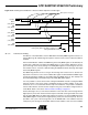
36.7.4.1 Timestamping Mode
Each mailbox has its own timestamp value. Each time a message is sent or received by a
mailbox, the 16-bit value MTIMESTAMP of the CAN_TIMESTP register is transferred to the
LSB bits of the CAN_MSRx register. The value read in the CAN_MSRx register corresponds
to the internal timer value at the Start Of Frame or the End Of Frame of the message handled
by the mailbox.
Figure 36-19. Mailbox Timestamp
MTCR
(CAN_MCRx)
MRDY
(CAN_MSRx)
CAN BUS
Remote Frame
Message x
Message y
Message y
(CAN_MDLx
CAN_MDHx)
MMI
(CAN_MSRx)
Remote Frame
Message x
TEOF
(CAN_MR)
MTIMESTAMP
(CAN_MSRx)
CAN_TIM
CAN BUS
MTIMESTAMP
(CAN_MSRy)
Message 1
Message 2
Start of Frame
TIMESTAMP
(CAN_TSTP)
End of Frame
Timestamp 1
Timestamp 1
Timestamp 2
Timestamp 2