
User manual

Using the AT90USBKey
2-12 AT90USBKey Hardware User Guide
7627A–AVR–04/06
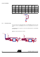
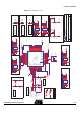
Figure 2-8 . Thermistor Schematic
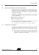
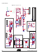
2.4.5 Data Flash memory
For mass-storage class demonstration purpose, the AT90USBKey provides two on-chip
serial Flash memories (AT45DB642D) connected to the AT90USB Serial Port Interface
(SPI).
The data-flash chip select signals are connected to PortE bit 0 and bit 1 of the AT90USB
(See Figure 2-9).
Figure 2-9 . On-board data flash schematic
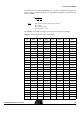
5 278,995 35 62,937 65 18,493 95 6,635
6 264,119 36 60,188 66 17,820 96 6,430
7 250,134 37 57,576 67 17,174 97 6,233
8 236,981 38 55,093 68 16,556 98 6,043
9 224,606 39 52,732 69 15,964 99 5,860
Temp.
(°C)
R
T
(KΩ)
Temp.
(°C)
R
T
(KΩ)
Temp.
(°C)
R
T
(KΩ)
Temp.
(°C)
R
T
(KΩ)
PF[7..0]
R29
R27
100k
PF0
VCC
PE0
VCC3
VCC3
PB[7..0]
PB1
R9
100k
RESET
PB3
PB2
SI
1
SCK
2
RESET
3
CS
4
WP
5
VCC
6
GND
7
SO
8
U2
AT45DB642D CASON8
PE1
VCC3
VCC3
RESET
PB1
R10
100k
PB3
PB2
SI
1
SCK
2
RESET
3
CS
4
WP
5
VCC
6
GND
7
SO
8
U3
AT45DB642D CASON8
R12
100k
R11
100k