
User manual

Using the AT90USBKey
2-10 AT90USBKey Hardware User Guide
7627A–AVR–04/06
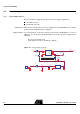
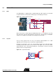
2.4.3 LEDs
The AT90USBKey includes 2 bi-color LEDs (green/red) implemented on one line. They
are connected to the high nibble of “Port D” of AT90USB (PORTD[4..7]).
To light on a LED, the corresponding port pin must drive a high level. To light off a LED,
the corresponding port pin must drive a low level.
Figure 2-7 . LEDs Implementation schematic
Table 2-1 . Leds references
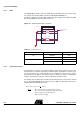
2.4.4 Temperature Sensor
The temperature sensor uses a thermistor (R29), or temperature-sensitive resistor. This
thermistor have a negative temperature coefficient (NTC), meaning the resistance goes
up as temperature goes down. Of all passive temperature measurement sensors,
thermistors have the highest sensitivity (resistance change per degree of temperature
change). Thermistors do not have a linear temperature/resistance curve.
The voltage over the NTC can be found using the A/D converter (connected to channel
0). See the AT90USB Datasheet for how to use the ADC. The thermistor value (R
T) is
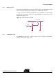
calculate with the following expression:
Where: RT = Thermistor value (Ω) at T temperature (°Kelvin)
R
H = Second resistor of the bridge -100 KΩ ±10% at 25°C
V
ADC0 = Voltage value on ADC-0 input (V)
VCC = Board power supply
LED Reference AT90USB Connection Color
D2 PORTD.4 Red
PORTD.5 Green
D5 PORTD.6 Green
PORTD.7 Red
D2
D5
R141k
R171k
LEDs
In-line Grouped LEDs
PD4
PD5
PD7
PD[7..0]
PD6
R221k
R231k
R
T
R
H
V
ADC0
⋅()VCC V
ADC0
()⁄=