
Datasheet

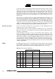
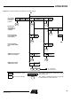
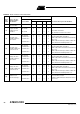
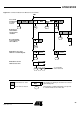
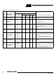
Table Of Contents
- Features
- Description
- Block Diagram
- SFR Mapping
- Pin Configurations
- Oscillators
- Enhanced Features
- Dual Data Pointer Register DPTR
- Expanded RAM (XRAM)
- Reset
- Power Monitor
- Timer 2
- Programmable Counter Array PCA
- Serial I/O Port
- Interrupt System
- Power Management
- Keyboard Interface
- 2-wire Interface (TWI)
- Serial Port Interface (SPI)
- Hardware Watchdog Timer
- ONCE(TM) Mode (ON Chip Emulation)
- Power-off Flag
- EEPROM Data Memory
- Reduced EMI Mode
- Flash Memory
- Electrical Characteristics
- Absolute Maximum Ratings
- DC Parameters
- AC Parameters
- Explanation of the AC Symbols
- External Program Memory Characteristics
- External Program Memory Read Cycle
- External Data Memory Characteristics
- External Data Memory Write Cycle
- External Data Memory Read Cycle
- Serial Port Timing - Shift Register Mode
- Shift Register Timing Waveforms
- External Clock Drive Waveforms
- AC Testing Input/Output Waveforms
- Float Waveforms
- Clock Waveforms
- Ordering Information
- Packaging Information
- Table of Contents
82
AT89C51ID2
4289C–8051–11/05
Description The CPU interfaces to the 2-wire logic via the following four 8-bit special function regis-
ters: the Synchronous Serial Control register (SSCON; Table 71), the Synchronous
Serial Data register (SSDAT; Table 72), the Synchronous Serial Control and Status reg-
ister (SSCS; Table 73) and the Synchronous Serial Address register (SSADR Table 76).
SSCON is used to enable the TWI interface, to program the bit rate (see Table 64), to
enable slave modes, to acknowledge or not a received data, to send a START or a
STOP condition on the 2-wire bus, and to acknowledge a serial interrupt. A hardware
reset disables the TWI module.
SSCS contains a status code which reflects the status of the 2-wire logic and the 2-wire
bus. The three least significant bits are always zero. The five most significant bits con-
tains the status code. There are 26 possible status codes. When SSCS contains F8h,
no relevant state information is available and no serial interrupt is requested. A valid sta-
tus code is available in SSCS one machine cycle after SI is set by hardware and is still
present one machine cycle after SI has been reset by software. to Table 70. give the
status for the master modes and miscellaneous states.
SSDAT contains a byte of serial data to be transmitted or a byte which has just been
received. It is addressable while it is not in process of shifting a byte. This occurs when
2-wire logic is in a defined state and the serial interrupt flag is set. Data in SSDAT
remains stable as long as SI is set. While data is being shifted out, data on the bus is
simultaneously shifted in; SSDAT always contains the last byte present on the bus.
SSADR may be loaded with the 7-bit slave address (7 most significant bits) to which the
TWI module will respond when programmed as a slave transmitter or receiver. The LSB
is used to enable general call address (00h) recognition.
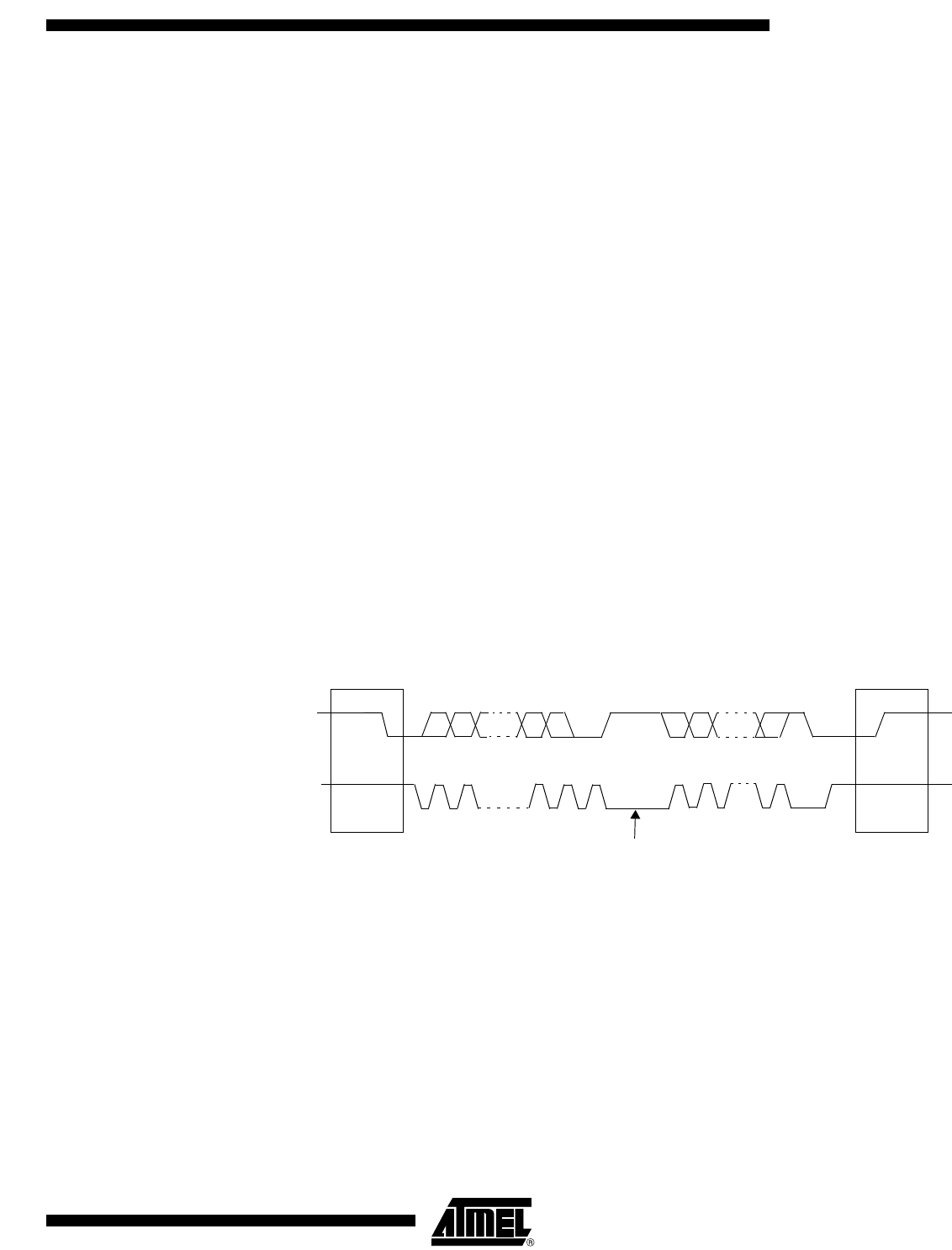
Figure 31 shows how a data transfer is accomplished on the 2-wire bus.
Figure 31. Complete Data Transfer on 2-wire Bus
The four operating modes are:
• Master Transmitter
• Master Receiver
• Slave transmitter
• Slave receiver
Data transfer in each mode of operation is shown in Table to Table 70 and Figure 32. to
Figure 35.. These figures contain the following abbreviations:
S : START condition
R : Read bit (high level at SDA)
SDA
SCL
S
start
condition
MSB
12
7
89
ACK
acknowledgement
signal from receiver
acknowledgement
signal from receiver
123-8 9
ACK
stop
condition
P
clock line held low
while interrupts are serviced