
Datasheet
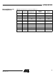
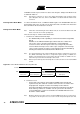
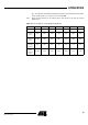
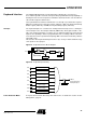
Table Of Contents
- Features
- Description
- Block Diagram
- SFR Mapping
- Pin Configurations
- Oscillators
- Enhanced Features
- Dual Data Pointer Register DPTR
- Expanded RAM (XRAM)
- Reset
- Power Monitor
- Timer 2
- Programmable Counter Array PCA
- Serial I/O Port
- Interrupt System
- Power Management
- Keyboard Interface
- 2-wire Interface (TWI)
- Serial Port Interface (SPI)
- Hardware Watchdog Timer
- ONCE(TM) Mode (ON Chip Emulation)
- Power-off Flag
- EEPROM Data Memory
- Reduced EMI Mode
- Flash Memory
- Electrical Characteristics
- Absolute Maximum Ratings
- DC Parameters
- AC Parameters
- Explanation of the AC Symbols
- External Program Memory Characteristics
- External Program Memory Read Cycle
- External Data Memory Characteristics
- External Data Memory Write Cycle
- External Data Memory Read Cycle
- Serial Port Timing - Shift Register Mode
- Shift Register Timing Waveforms
- External Clock Drive Waveforms
- AC Testing Input/Output Waveforms
- Float Waveforms
- Clock Waveforms
- Ordering Information
- Packaging Information
- Table of Contents
73
AT89C51ID2
4289C–8051–11/05
and RAM contents are preserved. The status of the Port pins during Power-Down mode
is detailed in Table 57.
Note: VCC may be reduced to as low as V
RET
during Power-Down mode to further reduce
power dissipation. Take care, however, that VDD is not reduced until Power-Down mode
is invoked.
Entering Power-Down Mode To enter Power-Down mode, set PD bit in PCON register. The AT89C51ID2 enters the
Power-Down mode upon execution of the instruction that sets PD bit. The instruction
that sets PD bit is the last instruction executed.
Exiting Power-Down Mode
Note: If VCC was reduced during the Power-Down mode, do not exit Power-Down mode until
VCC is restored to the normal operating level.
There are two ways to exit the Power-Down mode:
1. Generate an enabled external interrupt.
– The AT89C51ID2 provides capability to exit from Power-Down using INT0#,
INT1#.
Hardware clears PD bit in PCON register which starts the oscillator and
restores the clocks to the CPU and peripherals. Using INTx# input,
execution resumes when the input is released (see Figure 26). Execution
resumes with the interrupt service routine. Upon completion of the interrupt
service routine, program execution resumes with the instruction immediately
following the instruction that activated Power-Down mode.
Note: The external interrupt used to exit Power-Down mode must be configured as level sensi-
tive (INT0# and INT1#) and must be assigned the highest priority. In addition, the
duration of the interrupt must be long enough to allow the oscillator to stabilize. The exe-
cution will only resume when the interrupt is deasserted.
Note: Exit from power-down by external interrupt does not affect the SFRs nor the internal RAM
content.
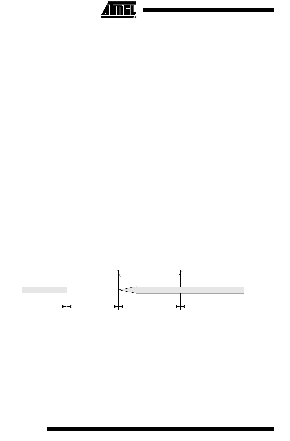
Figure 26. Power-Down Exit Waveform Using INT1:0#
2. Generate a reset.
– A logic high on the RST pin clears PD bit in PCON register directly and
asynchronously. This starts the oscillator and restores the clock to the CPU
and peripherals. Program execution momentarily resumes with the
instruction immediately following the instruction that activated Power-Down
mode and may continue for a number of clock cycles before the internal
reset algorithm takes control. Reset initializes the AT89C51ID2 and vectors
the CPU to address 0000h.
Note: During the time that execution resumes, the internal RAM cannot be accessed; however,
it is possible for the Port pins to be accessed. To avoid unexpected outputs at the Port
INT1:0#
OSC
Power-down phase Oscillator restart phase Active phaseActive phase