
Datasheet
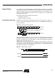
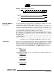
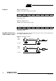

Table Of Contents
- Features
- Description
- Block Diagram
- SFR Mapping
- Pin Configurations
- Oscillators
- Enhanced Features
- Dual Data Pointer Register DPTR
- Expanded RAM (XRAM)
- Reset
- Power Monitor
- Timer 2
- Programmable Counter Array PCA
- Serial I/O Port
- Interrupt System
- Power Management
- Keyboard Interface
- 2-wire Interface (TWI)
- Serial Port Interface (SPI)
- Hardware Watchdog Timer
- ONCE(TM) Mode (ON Chip Emulation)
- Power-off Flag
- EEPROM Data Memory
- Reduced EMI Mode
- Flash Memory
- Electrical Characteristics
- Absolute Maximum Ratings
- DC Parameters
- AC Parameters
- Explanation of the AC Symbols
- External Program Memory Characteristics
- External Program Memory Read Cycle
- External Data Memory Characteristics
- External Data Memory Write Cycle
- External Data Memory Read Cycle
- Serial Port Timing - Shift Register Mode
- Shift Register Timing Waveforms
- External Clock Drive Waveforms
- AC Testing Input/Output Waveforms
- Float Waveforms
- Clock Waveforms
- Ordering Information
- Packaging Information
- Table of Contents
51
AT89C51ID2
4289C–8051–11/05
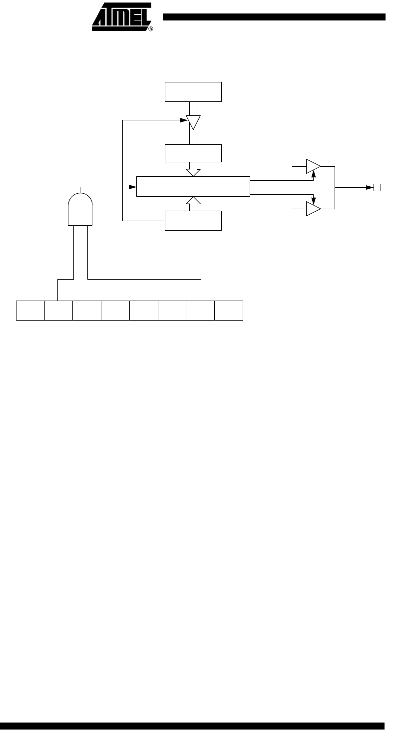
Figure 19. PCA PWM Mode
PCA Watchdog Timer An on-board watchdog timer is available with the PCA to improve the reliability of the
system without increasing chip count. Watchdog timers are useful for systems that are
susceptible to noise, power glitches, or electrostatic discharge. Module 4 is the only
PCA module that can be programmed as a watchdog. However, this module can still be
used for other modes if the watchdog is not needed. Figure 17 shows a diagram of how
the watchdog works. The user pre-loads a 16-bit value in the compare registers. Just
like the other compare modes, this 16-bit value is compared to the PCA timer value. If a
match is allowed to occur, an internal reset will be generated. This will not cause the
RST pin to be driven high.
In order to hold off the reset, the user has three options:
1. periodically change the compare value so it will never match the PCA timer,
2. periodically change the PCA timer value so it will never match the compare values, or
3. disable the watchdog by clearing the WDTE bit before a match occurs and then re-
enable it.
The first two options are more reliable because the watchdog timer is never disabled as
in option #3. If the program counter ever goes astray, a match will eventually occur and
cause an internal reset. The second option is also not recommended if other PCA mod-
ules are being used. Remember, the PCA timer is the time base for all modules;
changing the time base for other modules would not be a good idea. Thus, in most appli-
cations the first solution is the best option.
This watchdog timer won’t generate a reset out on the reset pin.
CL
CCAPnH
CCAPnL
ECOMn
CCAPMn, n= 0 to 4
0xDA to 0xDE
CAPNn MATn TOGn PWMn ECCFnCAPPn
8 bit comparator
CEXn
“0”
“1”
Enable
PCA counter/timer
Overflow