
Datasheet
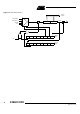
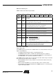
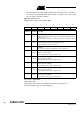
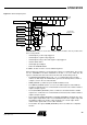
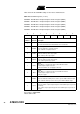
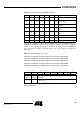
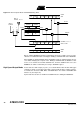
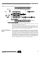
Table Of Contents
- Features
- Description
- Block Diagram
- SFR Mapping
- Pin Configurations
- Oscillators
- Enhanced Features
- Dual Data Pointer Register DPTR
- Expanded RAM (XRAM)
- Reset
- Power Monitor
- Timer 2
- Programmable Counter Array PCA
- Serial I/O Port
- Interrupt System
- Power Management
- Keyboard Interface
- 2-wire Interface (TWI)
- Serial Port Interface (SPI)
- Hardware Watchdog Timer
- ONCE(TM) Mode (ON Chip Emulation)
- Power-off Flag
- EEPROM Data Memory
- Reduced EMI Mode
- Flash Memory
- Electrical Characteristics
- Absolute Maximum Ratings
- DC Parameters
- AC Parameters
- Explanation of the AC Symbols
- External Program Memory Characteristics
- External Program Memory Read Cycle
- External Data Memory Characteristics
- External Data Memory Write Cycle
- External Data Memory Read Cycle
- Serial Port Timing - Shift Register Mode
- Shift Register Timing Waveforms
- External Clock Drive Waveforms
- AC Testing Input/Output Waveforms
- Float Waveforms
- Clock Waveforms
- Ordering Information
- Packaging Information
- Table of Contents
46
AT89C51ID2
4289C–8051–11/05
Table 30. PCA Module Modes (CCAPMn Registers)
There are two additional registers associated with each of the PCA modules. They are
CCAPnH and CCAPnL and these are the registers that store the 16-bit count when a
capture occurs or a compare should occur. When a module is used in the PWM mode
these registers are used to control the duty cycle of the output (See Table 31 &
Table 32).
Table 31. CCAPnH Registers (n = 0-4)
CCAP0H - PCA Module 0 Compare/Capture Control Register High (0FAh)
CCAP1H - PCA Module 1 Compare/Capture Control Register High (0FBh)
CCAP2H - PCA Module 2 Compare/Capture Control Register High (0FCh)
CCAP3H - PCA Module 3 Compare/Capture Control Register High (0FDh)
CCAP4H - PCA Module 4 Compare/Capture Control Register High (0FEh)
Reset Value = 0000 0000b
Not bit addressable
ECOMn CAPPn CAPNn MATn TOGn PWMm ECCFn Module Function
0000000 No Operation
X10000X
16-bit capture by a positive-edge
trigger on CEXn
X01000X
16-bit capture by a negative trigger
on CEXn
X11000X
16-bit capture by a transition on
CEXn
100100X
16-bit Software Timer / Compare
mode.
1 0 0 1 1 0 X 16-bit High Speed Output
1000010 8-bit PWM
1 0 0 1 X 0 X Watchdog Timer (module 4 only)
76543210
--------
Bit
Number
Bit
Mnemonic Description
7-0 -
PCA Module n Compare/Capture Control
CCAPnH Value