
Datasheet
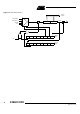
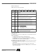
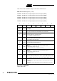
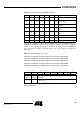
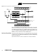
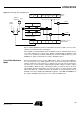
Table Of Contents
- Features
- Description
- Block Diagram
- SFR Mapping
- Pin Configurations
- Oscillators
- Enhanced Features
- Dual Data Pointer Register DPTR
- Expanded RAM (XRAM)
- Reset
- Power Monitor
- Timer 2
- Programmable Counter Array PCA
- Serial I/O Port
- Interrupt System
- Power Management
- Keyboard Interface
- 2-wire Interface (TWI)
- Serial Port Interface (SPI)
- Hardware Watchdog Timer
- ONCE(TM) Mode (ON Chip Emulation)
- Power-off Flag
- EEPROM Data Memory
- Reduced EMI Mode
- Flash Memory
- Electrical Characteristics
- Absolute Maximum Ratings
- DC Parameters
- AC Parameters
- Explanation of the AC Symbols
- External Program Memory Characteristics
- External Program Memory Read Cycle
- External Data Memory Characteristics
- External Data Memory Write Cycle
- External Data Memory Read Cycle
- Serial Port Timing - Shift Register Mode
- Shift Register Timing Waveforms
- External Clock Drive Waveforms
- AC Testing Input/Output Waveforms
- Float Waveforms
- Clock Waveforms
- Ordering Information
- Packaging Information
- Table of Contents

45
AT89C51ID2
4289C–8051–11/05
Table 29 shows the CCAPMn settings for the various PCA functions.
Table 29. CCAPMn Registers (n = 0-4)
CCAPM0 - PCA Module 0 Compare/Capture Control Register (0DAh)
CCAPM1 - PCA Module 1 Compare/Capture Control Register (0DBh)
CCAPM2 - PCA Module 2 Compare/Capture Control Register (0DCh)
CCAPM3 - PCA Module 3 Compare/Capture Control Register (0DDh)
CCAPM4 - PCA Module 4 Compare/Capture Control Register (0DEh)
Reset Value = X000 0000b
Not bit addressable
76543210
- ECOMn CAPPn CAPNn MATn TOGn PWMn ECCFn
Bit
Number
Bit
Mnemonic Description
7-
Reserved
The value read from this bit is indeterminate. Do not set this bit.
6ECOMn
Enable Comparator
Cleared to disable the comparator function.
Set to enable the comparator function.
5 CAPPn
Capture Positive
Cleared to disable positive edge capture.
Set to enable positive edge capture.
4 CAPNn
Capture Negative
Cleared to disable negative edge capture.
Set to enable negative edge capture.
3MATn
Match
When MATn = 1, a match of the PCA counter with this module's
compare/capture register causes the
CCFn bit in CCON to be set, flagging an interrupt.
2TOGn
Toggle
When TOGn = 1, a match of the PCA counter with this module's
compare/capture register causes the
CEXn pin to toggle.
1PWMn
Pulse Width Modulation Mode
Cleared to disable the CEXn pin to be used as a pulse width modulated output.
Set to enable the CEXn pin to be used as a pulse width modulated output.
0 CCF0
Enable CCF interrupt
Cleared to disable compare/capture flag CCFn in the CCON register to generate
an interrupt.
Set to enable compare/capture flag CCFn in the CCON register to generate an
interrupt.