
Datasheet
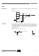
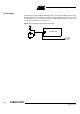
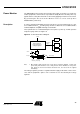

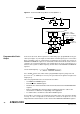
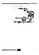
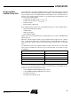
Table Of Contents
- Features
- Description
- Block Diagram
- SFR Mapping
- Pin Configurations
- Oscillators
- Enhanced Features
- Dual Data Pointer Register DPTR
- Expanded RAM (XRAM)
- Reset
- Power Monitor
- Timer 2
- Programmable Counter Array PCA
- Serial I/O Port
- Interrupt System
- Power Management
- Keyboard Interface
- 2-wire Interface (TWI)
- Serial Port Interface (SPI)
- Hardware Watchdog Timer
- ONCE(TM) Mode (ON Chip Emulation)
- Power-off Flag
- EEPROM Data Memory
- Reduced EMI Mode
- Flash Memory
- Electrical Characteristics
- Absolute Maximum Ratings
- DC Parameters
- AC Parameters
- Explanation of the AC Symbols
- External Program Memory Characteristics
- External Program Memory Read Cycle
- External Data Memory Characteristics
- External Data Memory Write Cycle
- External Data Memory Read Cycle
- Serial Port Timing - Shift Register Mode
- Shift Register Timing Waveforms
- External Clock Drive Waveforms
- AC Testing Input/Output Waveforms
- Float Waveforms
- Clock Waveforms
- Ordering Information
- Packaging Information
- Table of Contents
36
AT89C51ID2
4289C–8051–11/05
Figure 12. Auto-Reload Mode Up/Down Counter (DCEN = 1)
Programmable Clock-
Output
In the clock-out mode, Timer 2 operates as a 50%-duty-cycle, programmable clock gen-
erator (See Figure 13). The input clock increments TL2 at frequency F
CLK PERIPH
/2.The
timer repeatedly counts to overflow from a loaded value. At overflow, the contents of
RCAP2H and RCAP2L registers are loaded into TH2 and TL2.In this mode, Timer 2
overflows do not generate interrupts. The formula gives the clock-out frequency as a
function of the system oscillator frequency and the value in the RCAP2H and RCAP2L
registers:
For a 16 MHz system clock, Timer 2 has a programmable frequency range of 61 Hz
(F
CLK PERIPH
/2
16
) to 4 MHz (F
CLK PERIPH
/4). The generated clock signal is brought out to
T2 pin (P1.0).
Timer 2 is programmed for the clock-out mode as follows:
• Set T2OE bit in T2MOD register.
• Clear C/T2
bit in T2CON register.
• Determine the 16-bit reload value from the formula and enter it in RCAP2H/RCAP2L
registers.
• Enter a 16-bit initial value in timer registers TH2/TL2.It can be the same as the
reload value or a different one depending on the application.
• To start the timer, set TR2 run control bit in T2CON register.
It is possible to use Timer 2 as a baud rate generator and a clock generator simulta-
neously. For this configuration, the baud rates and clock frequencies are not
independent since both functions use the values in the RCAP2H and RCAP2L registers.
(DOWN COUNTING RELOAD VALUE)
C/T2
TF2
TR2
T2
EXF2
TH2
(8-bit)
TL2
(8-bit)
RCAP2H
(8-bit)
RCAP2L
(8-bit)
FFh
(8-bit)
FFh
(8-bit)
TOGGLE
(UP COUNTING RELOAD VALUE)
TIMER 2
INTERRUPT
F
CLK PERIPH
0
1
T2CON
T2CON
T2CON
T2CON
T2EX:
if DCEN=1, 1=UP
if DCEN=1, 0=DOWN
if DCEN = 0, up counting
:6
Clock O– utFrequency
F
CLKPERIPH
4 65536 RCAP2HRCAP2L⁄)–(×
---------------------------------------------------------------------------------------------
=