
Datasheet
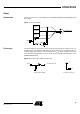

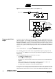
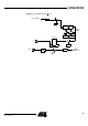
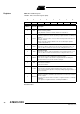
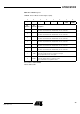
Table Of Contents
- Features
- Description
- Block Diagram
- SFR Mapping
- Pin Configurations
- Oscillators
- Enhanced Features
- Dual Data Pointer Register DPTR
- Expanded RAM (XRAM)
- Reset
- Power Monitor
- Timer 2
- Programmable Counter Array PCA
- Serial I/O Port
- Interrupt System
- Power Management
- Keyboard Interface
- 2-wire Interface (TWI)
- Serial Port Interface (SPI)
- Hardware Watchdog Timer
- ONCE(TM) Mode (ON Chip Emulation)
- Power-off Flag
- EEPROM Data Memory
- Reduced EMI Mode
- Flash Memory
- Electrical Characteristics
- Absolute Maximum Ratings
- DC Parameters
- AC Parameters
- Explanation of the AC Symbols
- External Program Memory Characteristics
- External Program Memory Read Cycle
- External Data Memory Characteristics
- External Data Memory Write Cycle
- External Data Memory Read Cycle
- Serial Port Timing - Shift Register Mode
- Shift Register Timing Waveforms
- External Clock Drive Waveforms
- AC Testing Input/Output Waveforms
- Float Waveforms
- Clock Waveforms
- Ordering Information
- Packaging Information
- Table of Contents

35
AT89C51ID2
4289C–8051–11/05
Timer 2 The Timer 2 in the AT89C51ID2 is the standard C52 Timer 2.
It is a 16-bit timer/counter: the count is maintained by two eight-bit timer registers, TH2
and TL2 are cascaded. It is controlled by T2CON (Table 25) and T2MOD (Table 26)
registers. Timer 2 operation is similar to Timer 0 and Timer 1.C/T2
selects F
OSC
/12
(timer operation) or external pin T2 (counter operation) as the timer clock input. Setting
TR2 allows TL2 to increment by the selected input.
Timer 2 has 3 operating modes: capture, autoreload and Baud Rate Generator. These
modes are selected by the combination of RCLK, TCLK and CP/RL2
(T2CON).
Refer to the Atmel 8-bit Microcontroller Hardware description for the description of Cap-
ture and Baud Rate Generator Modes.
Timer 2 includes the following enhancements:
• Auto-reload mode with up or down counter
• Programmable clock-output
Auto-Reload Mode The auto-reload mode configures Timer 2 as a 16-bit timer or event counter with auto-
matic reload. If DCEN bit in T2MOD is cleared, Timer 2 behaves as in 80C52 (refer to
the Atmel C51 Microcontroller Hardware description). If DCEN bit is set, Timer 2 acts as
an Up/down timer/counter as shown in Figure 12. In this mode the T2EX pin controls the
direction of count.
When T2EX is high, Timer 2 counts up. Timer overflow occurs at FFFFh which sets the
TF2 flag and generates an interrupt request. The overflow also causes the 16-bit value
in RCAP2H and RCAP2L registers to be loaded into the timer registers TH2 and TL2.
When T2EX is low, Timer 2 counts down. Timer underflow occurs when the count in the
timer registers TH2 and TL2 equals the value stored in RCAP2H and RCAP2L registers.
The underflow sets TF2 flag and reloads FFFFh into the timer registers.
The EXF2 bit toggles when Timer 2 overflows or underflows according to the direction of
the count. EXF2 does not generate any interrupt. This bit can be used to provide 17-bit
resolution.