
Datasheet
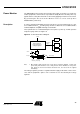

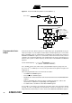
Table Of Contents
- Features
- Description
- Block Diagram
- SFR Mapping
- Pin Configurations
- Oscillators
- Enhanced Features
- Dual Data Pointer Register DPTR
- Expanded RAM (XRAM)
- Reset
- Power Monitor
- Timer 2
- Programmable Counter Array PCA
- Serial I/O Port
- Interrupt System
- Power Management
- Keyboard Interface
- 2-wire Interface (TWI)
- Serial Port Interface (SPI)
- Hardware Watchdog Timer
- ONCE(TM) Mode (ON Chip Emulation)
- Power-off Flag
- EEPROM Data Memory
- Reduced EMI Mode
- Flash Memory
- Electrical Characteristics
- Absolute Maximum Ratings
- DC Parameters
- AC Parameters
- Explanation of the AC Symbols
- External Program Memory Characteristics
- External Program Memory Read Cycle
- External Data Memory Characteristics
- External Data Memory Write Cycle
- External Data Memory Read Cycle
- Serial Port Timing - Shift Register Mode
- Shift Register Timing Waveforms
- External Clock Drive Waveforms
- AC Testing Input/Output Waveforms
- Float Waveforms
- Clock Waveforms
- Ordering Information
- Packaging Information
- Table of Contents
33
AT89C51ID2
4289C–8051–11/05
Power Monitor The POR/PFD function monitors the internal power-supply of the CPU core memories
and the peripherals, and if needed, suspends their activity when the internal power sup-
ply falls below a safety threshold. This is achieved by applying an internal reset to them.
By generating the Reset the Power Monitor insures a correct start up when
AT89C51ID2 is powered up.
Description In order to startup and maintain the microcontroller in correct operating mode, V
CC
has
to be stabilized in the V
CC
operating range and the oscillator has to be stabilized with a
nominal amplitude compatible with logic level VIH/VIL.
These parameters are controlled during the three phases: power-up, normal operation
and power going down. See Figure 10.
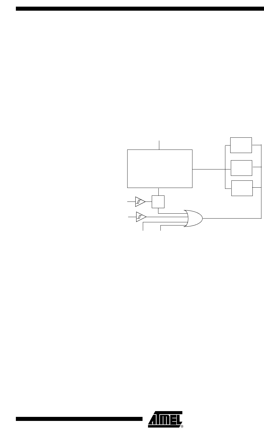
Figure 10. Power Monitor Block Diagram
Note: 1. Once XTAL1 High and low levels reach above and below VIH/VIL. a 1024 clock
period delay will extend the reset coming from the Power Fail Detect. If the power
falls below the Power Fail Detect threshold level, the Reset will be applied
immediately.
The Voltage regulator generates a regulated internal supply for the CPU core the mem-
ories and the peripherals. Spikes on the external Vcc are smoothed by the voltage
regulator.
VCC
Power On Reset
Power Fail Detect
Voltage Regulator
XTAL1
(1)
CPU core
Memories
Peripherals
Regulated
Supply
RST pin
Hardware
Watchdog
PCA
Watchdog
Internal Reset