
Datasheet
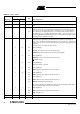
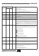
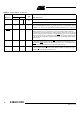
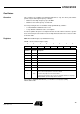
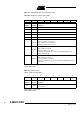
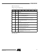
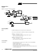
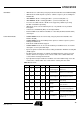
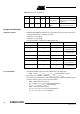
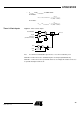
Table Of Contents
- Features
- Description
- Block Diagram
- SFR Mapping
- Pin Configurations
- Oscillators
- Enhanced Features
- Dual Data Pointer Register DPTR
- Expanded RAM (XRAM)
- Reset
- Power Monitor
- Timer 2
- Programmable Counter Array PCA
- Serial I/O Port
- Interrupt System
- Power Management
- Keyboard Interface
- 2-wire Interface (TWI)
- Serial Port Interface (SPI)
- Hardware Watchdog Timer
- ONCE(TM) Mode (ON Chip Emulation)
- Power-off Flag
- EEPROM Data Memory
- Reduced EMI Mode
- Flash Memory
- Electrical Characteristics
- Absolute Maximum Ratings
- DC Parameters
- AC Parameters
- Explanation of the AC Symbols
- External Program Memory Characteristics
- External Program Memory Read Cycle
- External Data Memory Characteristics
- External Data Memory Write Cycle
- External Data Memory Read Cycle
- Serial Port Timing - Shift Register Mode
- Shift Register Timing Waveforms
- External Clock Drive Waveforms
- AC Testing Input/Output Waveforms
- Float Waveforms
- Clock Waveforms
- Ordering Information
- Packaging Information
- Table of Contents
19
AT89C51ID2
4289C–8051–11/05
Design Considerations
Oscillators Control • PwdOscA and PwdOscB signals are generated in the Clock generator and used to
control the hard blocks of oscillators A and B.
• PwdOscA =’1’ stops OscA
• PwdOscB =’1’ stops OscB
• The following tables summarize the Operating modes:
Prescaler Divider • A hardware RESET puts the prescaler divider in the following state:
– CKRL = FFh: F
CLK CPU
= F
CLK PERIPH
= F
OSCA
/2 (Standard C51 feature)
• CKS signal selects OSCA or OSCB: F
CLK OUT
= F
OSCA
or F
OSCB
• Any value between FFh down to 00h can be written by software into CKRL register
in order to divide frequency of the selected oscillator:
– CKRL = 00h: minimum frequency
F
CLK CPU
= F
CLK PERIPH
= F
OSCA
/1020 (Standard Mode)
F
CLK CPU
= F
CLK PERIPH
= F
OSCA
/510 (X2 Mode)
– CKRL = FFh: maximum frequency
F
CLK CPU
= F
CLK PERIPH
= F
OSCA
/2 (Standard Mode)
F
CLK CPU
= F
CLK PERIPH
= F
OSCA
(X2 Mode)
0 1 1 X 0 IDLE MODE B
The CPU is off, OscB supplies the
peripherals, OscA can be disabled
(OscAEn = 0)
1XX 1X
POWER DOWN
MODE
The CPU and peripherals are off,
OscA and OscB are stopped
Table 20. Overview (Continued)
PCON.1 PCON.0 OscBEn OscAEn CKS Selected Mode Comment
PCON.1 OscAEn PwdOscA Comments
0 1 0 OscA running
1X1
OscA stopped by
Power-down mode
001
OscA stopped by
clearing OscAEn
PCON.1 OscBEn PwdOscB Comments
0 1 0 OscB running
1X1
OscB stopped by
Power-down mode
001
OscB stopped by
clearing OscBEn