
Datasheet
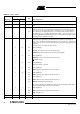
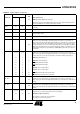
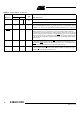
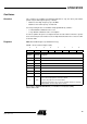
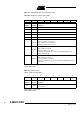
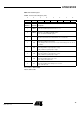
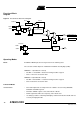
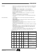
Table Of Contents
- Features
- Description
- Block Diagram
- SFR Mapping
- Pin Configurations
- Oscillators
- Enhanced Features
- Dual Data Pointer Register DPTR
- Expanded RAM (XRAM)
- Reset
- Power Monitor
- Timer 2
- Programmable Counter Array PCA
- Serial I/O Port
- Interrupt System
- Power Management
- Keyboard Interface
- 2-wire Interface (TWI)
- Serial Port Interface (SPI)
- Hardware Watchdog Timer
- ONCE(TM) Mode (ON Chip Emulation)
- Power-off Flag
- EEPROM Data Memory
- Reduced EMI Mode
- Flash Memory
- Electrical Characteristics
- Absolute Maximum Ratings
- DC Parameters
- AC Parameters
- Explanation of the AC Symbols
- External Program Memory Characteristics
- External Program Memory Read Cycle
- External Data Memory Characteristics
- External Data Memory Write Cycle
- External Data Memory Read Cycle
- Serial Port Timing - Shift Register Mode
- Shift Register Timing Waveforms
- External Clock Drive Waveforms
- AC Testing Input/Output Waveforms
- Float Waveforms
- Clock Waveforms
- Ordering Information
- Packaging Information
- Table of Contents
17
AT89C51ID2
4289C–8051–11/05
Functional Block
Diagram
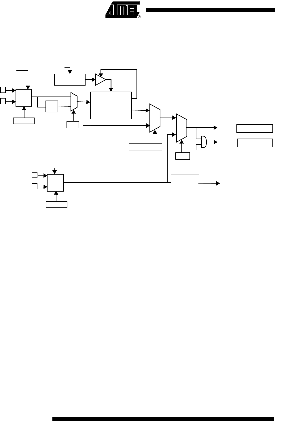
Figure 2. Functional Oscillator Block Diagram
Operating Modes
Reset A hardware RESET puts the Clock generator in the following state:
The selected oscillator depends on OSC bit in Hardware Security Byte (HSB).
HSB.OSC = 1 (Oscillator A selected)
• OscAEn = 1 & OscBEn = 0: OscA is running, OscB is stopped.
• CKS = 1: OscA is selected for CPU.
HSB.OSC = 0 (Oscillator B selected)
• OscAEn = 0 & OscBEn = 1: OscB is running, OscA is stopped.
• CKS = 0: OscB is selected for CPU.
Functional Modes
Normal Modes • CPU and Peripherals clock depend on the software selection using CKCON0,
CKCON1 and CKRL registers
• CKS bit in CKSEL register selects either OscA or OscB
• CKRL register determines the frequency of the OscA clock.
• It is always possible to switch dynamically by software from OscA to OscB, and vice
versa by changing CKS bit.
XtalA2
XtalA1
XtalB1
XtalB2
OscBEn
OscB
OscA
CLK
CLK
Idle
CPU clock
OscAEn
CKS
CKRL
Reload
8-bit
Prescaler-Divider
Reset
Peripheral Clock
1
0
:128
Sub
Clock
:2
X2
0
1
FOSCA
PERIPH
CPU
FOSCB
OSCCON
OSCCON
CKCON0
CKSEL
PwdOscA
PwdOscB
CKRL=0xFF?
0
1