
Datasheet
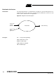
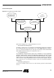
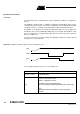
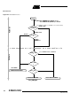
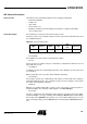
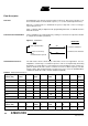
Table Of Contents
- Features
- Description
- Block Diagram
- SFR Mapping
- Pin Configurations
- Oscillators
- Enhanced Features
- Dual Data Pointer Register DPTR
- Expanded RAM (XRAM)
- Reset
- Power Monitor
- Timer 2
- Programmable Counter Array PCA
- Serial I/O Port
- Interrupt System
- Power Management
- Keyboard Interface
- 2-wire Interface (TWI)
- Serial Port Interface (SPI)
- Hardware Watchdog Timer
- ONCE(TM) Mode (ON Chip Emulation)
- Power-off Flag
- EEPROM Data Memory
- Reduced EMI Mode
- Flash Memory
- Electrical Characteristics
- Absolute Maximum Ratings
- DC Parameters
- AC Parameters
- Explanation of the AC Symbols
- External Program Memory Characteristics
- External Program Memory Read Cycle
- External Data Memory Characteristics
- External Data Memory Write Cycle
- External Data Memory Read Cycle
- Serial Port Timing - Shift Register Mode
- Shift Register Timing Waveforms
- External Clock Drive Waveforms
- AC Testing Input/Output Waveforms
- Float Waveforms
- Clock Waveforms
- Ordering Information
- Packaging Information
- Table of Contents
130
AT89C51ID2
4289C–8051–11/05
Command Data Stream
Protocol
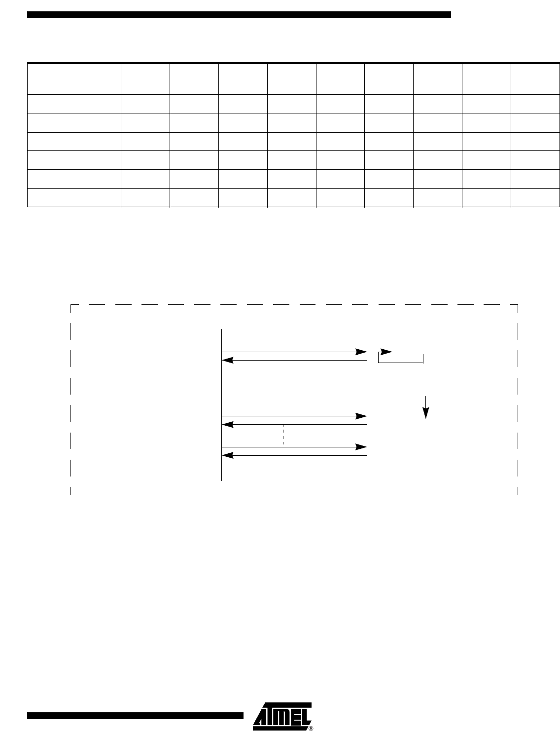
All commands are sent using the same flow. Each frame sent by the host is echoed by
the bootloader.
Figure 52. Command Flow
4800 OKOKOKOKOKOKOKOKOK
9600 OKOKOKOKOKOKOKOKOK
19200 OK OK OK OK OK OK OK OK OK
38400 - - OK OK OK OK OK OK OK
57600 - - OK - OKOKOKOKOK
115200 --OK-OK----
Table 95. Autobaud Performances (Continued)
Frequency (MHz)
Baudrate (kHz) 1.8432 2 2.4576 3 3.6864 4 5 6 7.3728
Bootloader
":"
Sends first character of the
Frame
If (not received ":")
Sends frame (made of 2 ASCII
Gets frame, and sends back e
c
for each received byte
Host
Else
":"
Sends echo and start
reception
characters per byte)
Echo analysis