
Datasheet
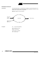
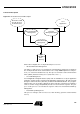
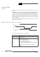
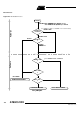
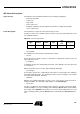
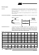
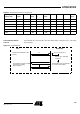
Table Of Contents
- Features
- Description
- Block Diagram
- SFR Mapping
- Pin Configurations
- Oscillators
- Enhanced Features
- Dual Data Pointer Register DPTR
- Expanded RAM (XRAM)
- Reset
- Power Monitor
- Timer 2
- Programmable Counter Array PCA
- Serial I/O Port
- Interrupt System
- Power Management
- Keyboard Interface
- 2-wire Interface (TWI)
- Serial Port Interface (SPI)
- Hardware Watchdog Timer
- ONCE(TM) Mode (ON Chip Emulation)
- Power-off Flag
- EEPROM Data Memory
- Reduced EMI Mode
- Flash Memory
- Electrical Characteristics
- Absolute Maximum Ratings
- DC Parameters
- AC Parameters
- Explanation of the AC Symbols
- External Program Memory Characteristics
- External Program Memory Read Cycle
- External Data Memory Characteristics
- External Data Memory Write Cycle
- External Data Memory Read Cycle
- Serial Port Timing - Shift Register Mode
- Shift Register Timing Waveforms
- External Clock Drive Waveforms
- AC Testing Input/Output Waveforms
- Float Waveforms
- Clock Waveforms
- Ordering Information
- Packaging Information
- Table of Contents

123
AT89C51ID2
4289C–8051–11/05
Bootloader Functionality
Introduction
The bootloader can be activated by two means: Hardware conditions or regular boot
process.
The Hardware conditions (EA = 1, PSEN = 0) during the Reset# falling edge force the
on-chip bootloader execution. This allows an application to be built that will normally
execute the end user’s code but can be manually forced into default ISP operation.
As PSEN is a an output port in normal operating mode after reset, user application
should take care to release PSEN after falling edge of reset signal. The hardware condi-
tions are sampled at reset signal falling edge, thus they can be released at any time
when reset input is low.
To ensure correct microcontroller startup, the PSEN pin should not be tied to ground
during power-on (See Figure 48).
Figure 48. Hardware conditions typical sequence during power-on.
The on-chip bootloader boot process is shown Figure 49
VCC
PSEN
RST
Purpose
Hardware Conditions
The Hardware Conditions force the bootloader execution whatever BLJB,
BSB and SBV values.
BLJB
The Boot Loader Jump Bit forces the application execution.
BLJB = 0 => Boot loader execution.
BLJB = 1 => Application execution
The BLJB is a fuse bit in the Hardware Byte.
That can be modified by hardware (programmer) or by software (API).
Note:
The BLJB test is perform by hardware to prevent any program
execution..