
Datasheet


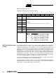

Table Of Contents
- Features
- Description
- Block Diagram
- SFR Mapping
- Pin Configurations
- Oscillators
- Enhanced Features
- Dual Data Pointer Register DPTR
- Expanded RAM (XRAM)
- Reset
- Power Monitor
- Timer 2
- Programmable Counter Array PCA
- Serial I/O Port
- Interrupt System
- Power Management
- Keyboard Interface
- 2-wire Interface (TWI)
- Serial Port Interface (SPI)
- Hardware Watchdog Timer
- ONCE(TM) Mode (ON Chip Emulation)
- Power-off Flag
- EEPROM Data Memory
- Reduced EMI Mode
- Flash Memory
- Electrical Characteristics
- Absolute Maximum Ratings
- DC Parameters
- AC Parameters
- Explanation of the AC Symbols
- External Program Memory Characteristics
- External Program Memory Read Cycle
- External Data Memory Characteristics
- External Data Memory Write Cycle
- External Data Memory Read Cycle
- Serial Port Timing - Shift Register Mode
- Shift Register Timing Waveforms
- External Clock Drive Waveforms
- AC Testing Input/Output Waveforms
- Float Waveforms
- Clock Waveforms
- Ordering Information
- Packaging Information
- Table of Contents

108
AT89C51ID2
4289C–8051–11/05
Table 83. WDTPRG Register
WDTPRG - Watchdog Timer Out Register (0A7h)
Reset value = XXXX X000
WDT During Power Down
and Idle
In Power Down mode the oscillator stops, which means the WDT also stops. While in
Power Down mode the user does not need to service the WDT. There are 2 methods of
exiting Power Down mode: by a hardware reset or via a level activated external inter-
rupt which is enabled prior to entering Power Down mode. When Power Down is exited
with hardware reset, servicing the WDT should occur as it normally should whenever the
AT89C51ID2 is reset. Exiting Power Down with an interrupt is significantly different. The
interrupt is held low long enough for the oscillator to stabilize. When the interrupt is
brought high, the interrupt is serviced. To prevent the WDT from resetting the device
while the interrupt pin is held low, the WDT is not started until the interrupt is pulled high.
It is suggested that the WDT be reset during the interrupt service routine.
To ensure that the WDT does not overflow within a few states of exiting of powerdown, it
is better to reset the WDT just before entering powerdown.
In the Idle mode, the oscillator continues to run. To prevent the WDT from resetting the
AT89C51ID2 while in Idle mode, the user should always set up a timer that will periodi-
cally exit Idle, service the WDT, and re-enter Idle mode.
76543210
- - - - - S2 S1 S0
Bit
Number
Bit
Mnemonic Description
7-
Reserved
The value read from this bit is undetermined. Do not try to set this bit.
6-
5-
4-
3-
2S2
WDT Time-out select bit 2
1S1WDT Time-out select bit 1
0S0WDT Time-out select bit 0
S2
S1 S0 Selected Time-out
00 0 (2
14
- 1) machine cycles, 16. 3 ms @ F
OSCA
=12 MHz
00 1 (2
15
- 1) machine cycles, 32.7 ms @ F
OSCA
=12 MHz
01 0 (2
16
- 1) machine cycles, 65. 5 ms @ F
OSCA
=12 MHz
01 1 (2
17
- 1) machine cycles, 131 ms @ F
OSCA
=12 MHz
10 0 (2
18
- 1) machine cycles, 262 ms @ F
OSCA
=12 MHz
10 1 (2
19
- 1) machine cycles, 542 ms @ F
OSCA
=12 MHz
11 0 (2
20
- 1) machine cycles, 1.05 s @ F
OSCA
=12 MHz
11 1 (2
21
- 1) machine cycles, 2.09 s @ F
OSCA
=12 MHz