
Datasheet

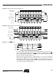
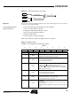
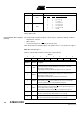

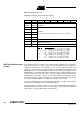

Table Of Contents
- Features
- Description
- Block Diagram
- SFR Mapping
- Pin Configurations
- Oscillators
- Enhanced Features
- Dual Data Pointer Register DPTR
- Expanded RAM (XRAM)
- Reset
- Power Monitor
- Timer 2
- Programmable Counter Array PCA
- Serial I/O Port
- Interrupt System
- Power Management
- Keyboard Interface
- 2-wire Interface (TWI)
- Serial Port Interface (SPI)
- Hardware Watchdog Timer
- ONCE(TM) Mode (ON Chip Emulation)
- Power-off Flag
- EEPROM Data Memory
- Reduced EMI Mode
- Flash Memory
- Electrical Characteristics
- Absolute Maximum Ratings
- DC Parameters
- AC Parameters
- Explanation of the AC Symbols
- External Program Memory Characteristics
- External Program Memory Read Cycle
- External Data Memory Characteristics
- External Data Memory Write Cycle
- External Data Memory Read Cycle
- Serial Port Timing - Shift Register Mode
- Shift Register Timing Waveforms
- External Clock Drive Waveforms
- AC Testing Input/Output Waveforms
- Float Waveforms
- Clock Waveforms
- Ordering Information
- Packaging Information
- Table of Contents

107
AT89C51ID2
4289C–8051–11/05
Hardware Watchdog
Timer
The WDT is intended as a recovery method in situations where the CPU may be sub-
jected to software upset. The WDT consists of a 14-bit counter and the WatchDog Timer
ReSeT (WDTRST) SFR. The WDT is by default disabled from exiting reset. To enable
the WDT, user must write 01EH and 0E1H in sequence to the WDTRST, SFR location
0A6H. When WDT is enabled, it will increment every machine cycle while the oscillator
is running and there is no way to disable the WDT except through reset (either hardware
reset or WDT overflow reset). When WDT overflows, it will drive an output RESET HIGH
pulse at the RST-pin.
Using the WDT To enable the WDT, user must write 01EH and 0E1H in sequence to the WDTRST, SFR
location 0A6H. When WDT is enabled, the user needs to service it by writing to 01EH
and 0E1H to WDTRST to avoid WDT overflow. The 14-bit counter overflows when it
reaches 16383 (3FFFH) and this will reset the device. When WDT is enabled, it will
increment every machine cycle while the oscillator is running. This means the user must
reset the WDT at least every 16383 machine cycle. To reset the WDT the user must
write 01EH and 0E1H to WDTRST. WDTRST is a write only register. The WDT counter
cannot be read or written. When WDT overflows, it will generate an output RESET pulse
at the RST-pin. The RESET pulse duration is 96 x T
CLK PERIPH
, where T
CLK PERIPH
= 1/F
CLK
PERIPH
. To make the best use of the WDT, it should be serviced in those sections of code
that will periodically be executed within the time required to prevent a WDT reset.
To have a more powerful WDT, a 2
7
counter has been added to extend the Time-out
capability, ranking from 16ms to 2s @ F
OSCA
= 12MHz. To manage this feature, refer to
WDTPRG register description, Table 82.
Table 82. WDTRST Register
WDTRST - Watchdog Reset Register (0A6h)
Reset Value = XXXX XXXXb
Write only, this SFR is used to reset/enable the WDT by writing 01EH then 0E1H in
sequence.
76543210
--------