
Datasheet

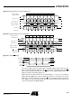
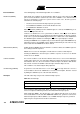
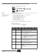
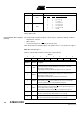

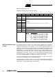

Table Of Contents
- Features
- Description
- Block Diagram
- SFR Mapping
- Pin Configurations
- Oscillators
- Enhanced Features
- Dual Data Pointer Register DPTR
- Expanded RAM (XRAM)
- Reset
- Power Monitor
- Timer 2
- Programmable Counter Array PCA
- Serial I/O Port
- Interrupt System
- Power Management
- Keyboard Interface
- 2-wire Interface (TWI)
- Serial Port Interface (SPI)
- Hardware Watchdog Timer
- ONCE(TM) Mode (ON Chip Emulation)
- Power-off Flag
- EEPROM Data Memory
- Reduced EMI Mode
- Flash Memory
- Electrical Characteristics
- Absolute Maximum Ratings
- DC Parameters
- AC Parameters
- Explanation of the AC Symbols
- External Program Memory Characteristics
- External Program Memory Read Cycle
- External Data Memory Characteristics
- External Data Memory Write Cycle
- External Data Memory Read Cycle
- Serial Port Timing - Shift Register Mode
- Shift Register Timing Waveforms
- External Clock Drive Waveforms
- AC Testing Input/Output Waveforms
- Float Waveforms
- Clock Waveforms
- Ordering Information
- Packaging Information
- Table of Contents

103
AT89C51ID2
4289C–8051–11/05
Error Conditions The following flags in the SPSTA signal SPI error conditions:
Mode Fault (MODF) Mode Fault error in Master mode SPI indicates that the level on the Slave Select (SS
)
pin is inconsistent with the actual mode of the device. MODF is set to warn that there
may be a multi-master conflict for system control. In this case, the SPI system is
affected in the following ways:
• An SPI receiver/error CPU interrupt request is generated
• The SPEN bit in SPCON is cleared. This disables the SPI
• The MSTR bit in SPCON is cleared
When SS
Disable (SSDIS) bit in the SPCON register is cleared, the MODF flag is set
when the SS
signal becomes ’0’.
However, as stated before, for a system with one Master, if the SS
pin of the Master
device is pulled low, there is no way that another Master attempts to drive the network.
In this case, to prevent the MODF flag from being set, software can set the SSDIS bit in
the SPCON register and therefore making the SS
pin as a general-purpose I/O pin.
Clearing the MODF bit is accomplished by a read of SPSTA register with MODF bit set,
followed by a write to the SPCON register. SPEN Control bit may be restored to its orig-
inal set state after the MODF bit has been cleared.
Write Collision (WCOL) A Write Collision (WCOL) flag in the SPSTA is set when a write to the SPDAT register is
done during a transmit sequence.
WCOL does not cause an interruption, and the transfer continues uninterrupted.
Clearing the WCOL bit is done through a software sequence of an access to SPSTA
and an access to SPDAT.
Overrun Condition An overrun condition occurs when the Master device tries to send several data Bytes
and the Slave devise has not cleared the SPIF bit issuing from the previous data Byte
transmitted. In this case, the receiver buffer contains the Byte sent after the SPIF bit was
last cleared. A read of the SPDAT returns this Byte. All others Bytes are lost.
This condition is not detected by the SPI peripheral.
SS Error Flag (SSERR) A Synchronous Serial Slave Error occurs when SS
goes high before the end of a
received data in slave mode. SSERR does not cause in interruption, this bit is cleared
by writing 0 to SPEN bit (reset of the SPI state machine).
Interrupts Two SPI status flags can generate a CPU interrupt requests:
Table 78. SPI Interrupts
Serial Peripheral data transfer flag, SPIF: This bit is set by hardware when a transfer
has been completed. SPIF bit generates transmitter CPU interrupt requests.
Mode Fault flag, MODF: This bit becomes set to indicate that the level on the SS is
inconsistent with the mode of the SPI. MODF with SSDIS reset, generates receiver/error
CPU interrupt requests. When SSDIS is set, no MODF interrupt request is generated.
Figure 42 gives a logical view of the above statements.
Flag Request
SPIF (SP data transfer) SPI Transmitter Interrupt request
MODF (Mode Fault) SPI Receiver/Error Interrupt Request (if SSDIS = ’0’)